
Propulsion system

A propeller and electric power technology, applied in the direction of ship propulsion, propulsion components, propulsion transmission devices, etc., to achieve the effects of improved hydrodynamic efficiency, efficient ship operation, and low power loss

Inactive Publication Date: 2013-11-27
ABB AS
View PDF5 Cites 4 Cited by
  • Summary
  • Abstract
  • Description
  • Claims
  • Application Information

AI Technical Summary

Problems solved by technology

At the same time, total energy consumption and electricity generation must be as efficient as possible

Method used


Image

  • Propulsion system
  • Propulsion system
  • Propulsion system

Examples


Embodiment Construction

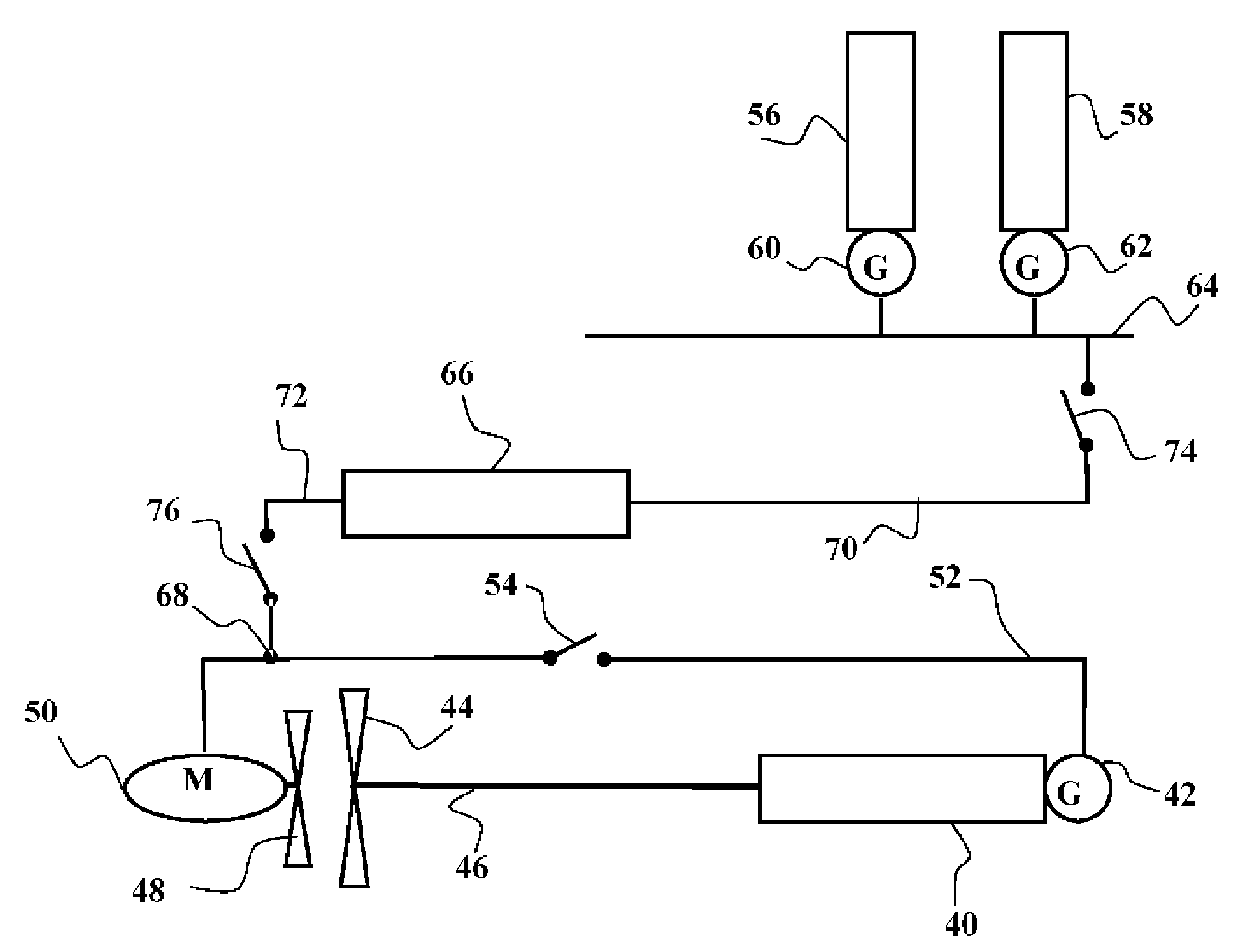
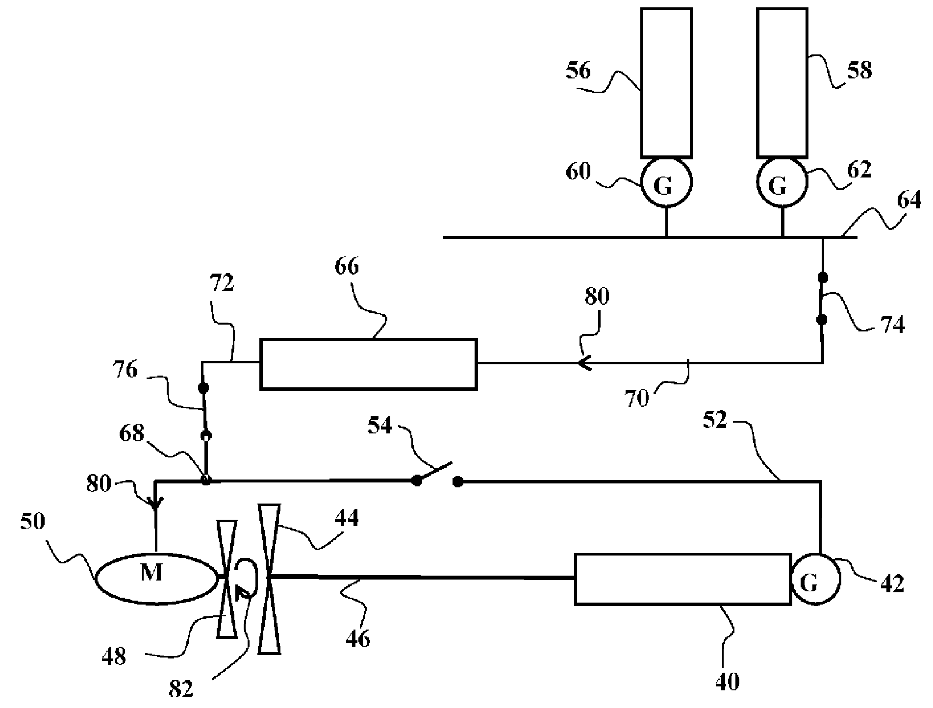
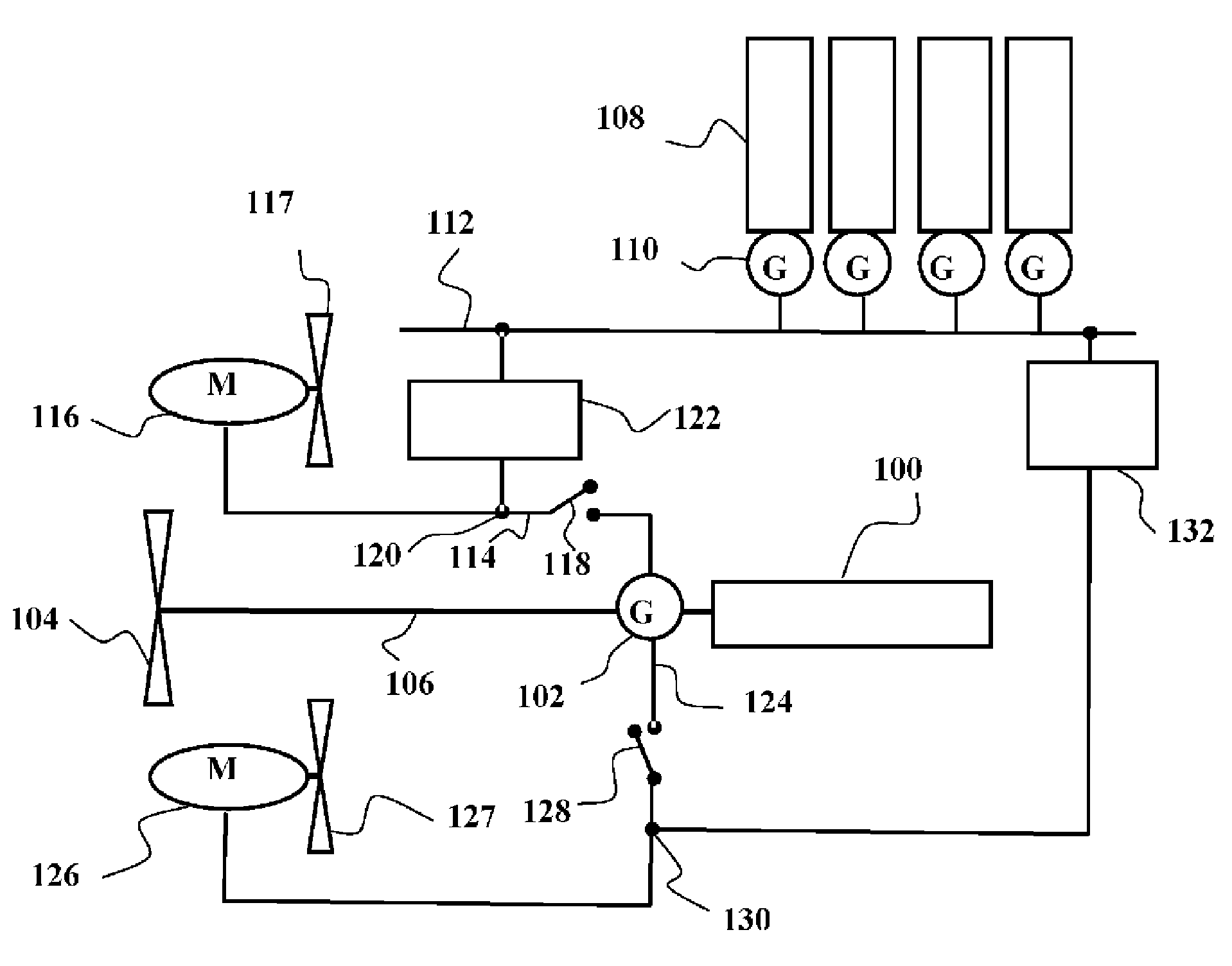
[0029] figure 1 A schematic diagram of a first preferred embodiment of the invention is shown. A rotating power unit 2 positioned inside the hull of a seagoing vessel rotates a generator 4 . The rotary power unit 2 is preferably a two-stroke diesel engine using oil as fuel. The rotating power unit may also be another engine using some primary energy source such as natural gas, nuclear or fuel cells. The generator 4 is connected to the output shaft of the rotating power unit 2 directly or through a gearbox. The rotational speed of the rotor of the generator 4 is thus the same as the rotational speed of the output shaft of the rotary power unit 2 or, when there is a gearbox, the ratio of their rotational speeds is defined by the transmission ratio of the gears. The electrical output of the generator 4 is connected to a propulsion motor 8 via an electrical power connection 6 . The propulsion motor 8 rotates a propeller 10 fixed to the shaft of the motor. A circuit breaker 12...


PUM


Abstract

Arrangement for supplying electric power to a propulsion system of a marine vessel, which comprises a propeller motor (8), which is connected to an ac generator (4) and the ac generator (4)supplies electric energy to the propeller motor (8).The ac generator is rotated by a rotating power unit (2).A frequency converter (26) is connectable parallel to the ac generator (4) and the frequency converter (26) supplies electric power from a second power unit (16,18).

Description

technical field [0001] The invention relates to an assembly of a propulsion system for supplying electrical power to a seagoing vessel. Background technique [0002] The propulsion power of large warships or seagoing ships is generated by rotating power units, and the energy sources of rotating power units are oil, natural gas, and nuclear energy. A rotating power unit may be a diesel engine, a gas turbine, or a turbine rotating a nuclear power reactor. The mechanical output shaft is coupled directly or via gears to the shaft of a propeller or rotary power unit that drives a generator that supplies electrical power to the ship's propulsion motors. Furthermore, several different combinations of these two main ways of driving propellers have been used. [0003] The power and energy efficiency of seagoing vessels requires that propulsion power be generated as economically as possible in the different modes of operation. The total energy consumption should therefore be optimi...

Claims


Application Information

Patent Timeline
Patent Type & Authority Applications(China)
IPC IPC(8): B63H5/10B63H21/20B63H23/24B63J3/02B60L50/13
CPCY02T90/38B63H5/10B63H23/24Y02T70/5281B63J3/02B63H21/20B60L11/08Y02T70/5236B60L2200/32B60L50/13Y02T70/50Y02T90/40
Inventor K.科基拉M.卡雅瓦S.卡纳瓦
Owner ABB AS
Learn More