
The Control Method of Midpoint Potential Balance of DC Side in NPC Three-level Structure

A control method and potential balance technology, which can be applied in the direction of converting AC power input to DC power output, photovoltaic power generation, electrical components, etc. Accuracy and other problems, to achieve the effect of eliminating DC offset and low-frequency fluctuation, simple and easy control algorithm, and improving the quality of output current

Active Publication Date: 2016-06-08
XIAN LONTEN RENEWABLE ENERGY TECH
View PDF3 Cites 0 Cited by
  • Summary
  • Abstract
  • Description
  • Claims
  • Application Information

AI Technical Summary

Problems solved by technology

Due to the inflow and outflow of current at the midpoint of the DC side, it is easy to cause the imbalance of the midpoint potential, which will have a very adverse impact on the performance and safety of the inverter. Therefore, the midpoint potential imbalance must be eliminated through appropriate control.
At present, the research on software control algorithms is relatively extensive. Some control the midpoint potential to fluctuate within a certain range by performing hysteresis comparison on the midpoint. This method is simple and easy to implement, but it does not completely eliminate the low-frequency fluctuation of the midpoint potential.
Some studies have also shown that the neutral point current can be controlled to zero by injecting zero-sequence voltage to achieve the balance of the mid-point potential. This method can completely eliminate the low-frequency fluctuation of the mid-point potential and achieve better control effects. The voltage control algorithm is relatively complex and not easy to apply in engineering, and the calculation of zero-sequence voltage will be inaccurate near the zero-crossing point of each phase modulation voltage

Method used


Image

  • The Control Method of Midpoint Potential Balance of DC Side in NPC Three-level Structure
  • The Control Method of Midpoint Potential Balance of DC Side in NPC Three-level Structure
  • The Control Method of Midpoint Potential Balance of DC Side in NPC Three-level Structure

Examples


Embodiment

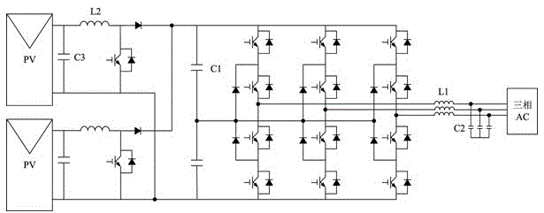
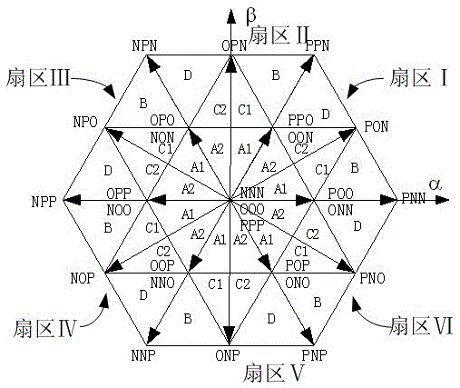
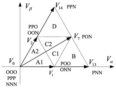
[0038] see figure 1, After the photovoltaic inverter is connected, the control chip will obtain the three-phase inductor current I through the sampling circuit a , I b , I c , and the small vector V that can affect the midpoint potential is obtained by calculation 1 , V 2 and in the vector V 7 The action time is t V1 , t V2 and t V7 , when they act, the currents corresponding to the midpoint are I a , I c and I b . You can do the following, see image 3 :

[0039] If m≤0.5, the reference voltage is located in the small triangle 1 of the first sector:

[0040] (1) If I a ·t V1 +I c ·t V2 >0, select V 1 As a redundant small vector for regulation, according to the required current I at the midpoint o , calculate the distribution coefficient of the redundant small vector

[0041] (2) If I a ·t V1 +I c ·t V2 ≤0, select V 2 As a redundant small vector for regulation, according to the required current I at the midpoint o , calculate the distribution coeffi...


PUM


Abstract

The invention relates to a control method for the midpoint potential balance of a DC side in an NPC three-level structure. The photovoltaic grid-connected inverter adopts the midpoint clamping type three-level inverter circuit, which easily causes the imbalance of the midpoint potential; Low-frequency fluctuations; the control algorithm for injecting zero-sequence voltage is relatively complicated. The control method of the midpoint potential balance of the DC side in the NPC three-level structure is characterized in that: the difference between the half of the bus voltage on the DC side of the photovoltaic inverter and the midpoint voltage is obtained, and the current switching cycle needs to be obtained through the PI regulator. For the current value injected at the midpoint, the action time of the redundant small vectors in each sector in the space vector pulse width modulation is used as the modulation means, and the distribution ratio of the redundant small vectors in one switching period is calculated. The invention eliminates the DC bias and low-frequency fluctuation of the diode-clamped three-level midpoint potential under the existing hardware conditions, and realizes the midpoint balance.

Description

technical field [0001] The invention relates to a method for controlling the midpoint potential fluctuation of the DC side of a diode-clamped (NPC) three-level inverter circuit, in particular to a control method for the midpoint potential balance of the DC side in the NPC three-level structure. Background technique [0002] Many photovoltaic grid-connected inverters use a neutral-point clamped three-level inverter circuit, and the input side uses a capacitor voltage divider, which can add a voltage to the output of the inverter. Level, so that the PWM waveform of the inverter output is closer to the sinusoidal waveform of the three-phase grid voltage than the traditional two-level. Due to the inflow and outflow of current at the midpoint of the DC side, it is easy to cause the imbalance of the midpoint potential, which will have a very adverse effect on the performance and safety of the inverter. Therefore, the midpoint potential imbalance must be eliminated through appropr...

Claims


Application Information

Patent Timeline
Patent Type & Authority Patents(China)
IPC IPC(8): H02M7/487
CPCH02M7/487H02M7/53876Y02E10/56
Inventor 徐西昌陈桥梁倪嘉
Owner XIAN LONTEN RENEWABLE ENERGY TECH
Learn More