
Fixed off-time peak current pulse sequence control method and device

A technology of fixed off time and pulse sequence, which is applied in the direction of control/regulation system, output power conversion device, electrical components, etc., to achieve the effect of eliminating low frequency fluctuation phenomenon and stable and reliable control

Inactive Publication Date: 2015-10-14
SOUTHWEST JIAOTONG UNIV
View PDF1 Cites 0 Cited by
  • Summary
  • Abstract
  • Description
  • Claims
  • Application Information

AI Technical Summary

Problems solved by technology

[0004] The purpose of this invention is to provide a kind of switching converter control method, make it overcome the technical shortcoming of existing pulse sequence control when CCM switching converter is applied

Method used


Image

  • Fixed off-time peak current pulse sequence control method and device
  • Fixed off-time peak current pulse sequence control method and device
  • Fixed off-time peak current pulse sequence control method and device

Examples


Embodiment Construction

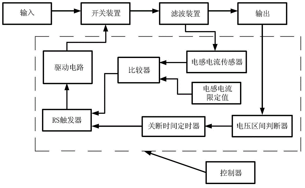
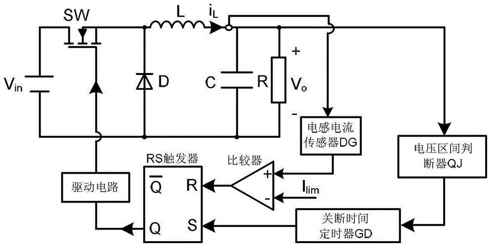
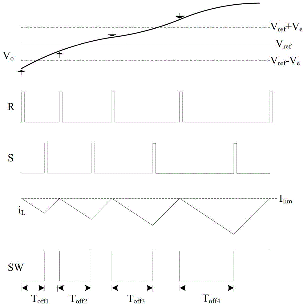
[0016] figure 1 It shows that the specific embodiment of the present invention is: a switching converter fixed off-time peak current type pulse sequence control method and its device, which are triggered by a voltage interval judge, an off-time timer, an inductive current sensor, a comparator, and a RS device and drive circuit. The voltage interval judge judges the voltage interval of the difference between the output voltage and the reference voltage to control the off-time timer, thereby determining the off-time in the current control pulse cycle. When the fixed off-time ends, RS The flip-flop is set, the output signal of the RS flip-flop controls the conduction of the switch tube after passing through the driving circuit, and the inductor current sensor detects the inductor current. When the inductor current rises to the limit value of the inductor current, the output level of the comparator is reversed, and the RS flip-flop is reset. The switch tube is turned off.

[001...


PUM


Abstract

The invention discloses a switching converter fixed turn-off time peak current type pulse sequence control method and a switching converter fixed turn-off time peak current type pulse sequence control device. The output voltage value detected at a starting moment of a switching period determines turn-off time in the switching period, and conduction time of a switching tube is determined together by inductive current and the inductive current limit value. The fixed turn-off time peak current type pulse sequence control method and the fixed turn-off time peak current type pulse sequence control device can be applied to DCM and CCM switching converters. The fixed turn-off time peak current type pulse sequence control method and the fixed turn-off time peak current type pulse sequence control device have the advantages of being stable and reliable in control, and capable of possessing the current limiting function and avoiding the low-frequency fluctuation phenomenon probably existing in pulse sequence control from a source.

Description

technical field [0001] The invention relates to an electronic switching device, especially a control method and device for a switching converter. Background technique [0002] The switching converter is an energy conversion device, which converts the input energy into energy suitable for the output requirements through appropriate conversion. Switching converters are widely used in real life because of their outstanding advantages such as small size, light weight, high conversion efficiency, and high power density. In people's daily life, switching converters are ubiquitous, such as computer adapters, battery chargers, etc. The switching converter is composed of two parts: the main circuit of the power converter and its control circuit. The main circuit completes energy conversion and transmission, while the control circuit ensures the stable operation of the main circuit and the energy conversion can meet the output requirements. For the same main circuit, the use of diff...

Claims


Application Information

Patent Timeline
Patent Type & Authority Patents(China)
IPC IPC(8): H02M1/08H02M3/155
Inventor 吴松荣何圣仲许建平周国华王金平
Owner SOUTHWEST JIAOTONG UNIV
Learn More