
Sensor fixing test rack for uniaxial compression sound emission test of coal petrography and application method of same

An acoustic emission sensor and uniaxial compression technology, which is applied in the direction of material analysis using acoustic emission technology, material analysis using sound wave/ultrasonic wave/infrasonic wave, instruments, etc. Inaccurate position fixation, increased sample loss and test time-consuming problems, to achieve the effect of improving test efficiency and success rate, reducing test time-consuming, and ensuring repeated use

Inactive Publication Date: 2013-11-27
CHINA UNIV OF MINING & TECH
View PDF5 Cites 30 Cited by
  • Summary
  • Abstract
  • Description
  • Claims
  • Application Information

AI Technical Summary

Problems solved by technology

At present, there is no device specially used for fixing acoustic emission sensors on the surface of standard cylindrical samples such as coal and rock. The surface of the acoustic emission sensor is fixed by coating solid butter on the surface of the sensor, and then fixed with a rubber band. During the process, the sensor falls off, and the acoustic emission sensor needs to be disassembled and assembled repeatedly. In this case, the sample loss and test time are increased, which affects the normal operation of the uniaxial compression acoustic emission test.

Method used


Image

  • Sensor fixing test rack for uniaxial compression sound emission test of coal petrography and application method of same
  • Sensor fixing test rack for uniaxial compression sound emission test of coal petrography and application method of same
  • Sensor fixing test rack for uniaxial compression sound emission test of coal petrography and application method of same

Examples


Embodiment Construction

[0021] An embodiment of the present invention will be further described below in conjunction with accompanying drawing:

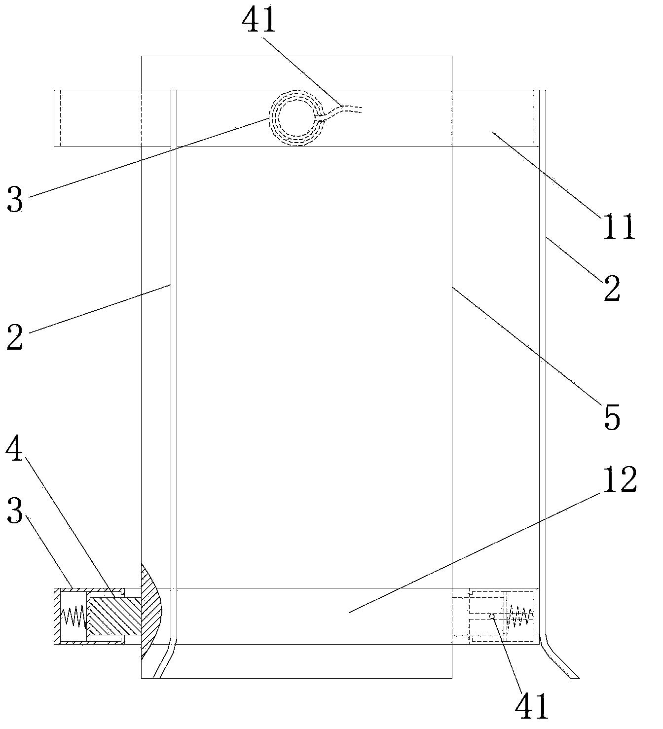
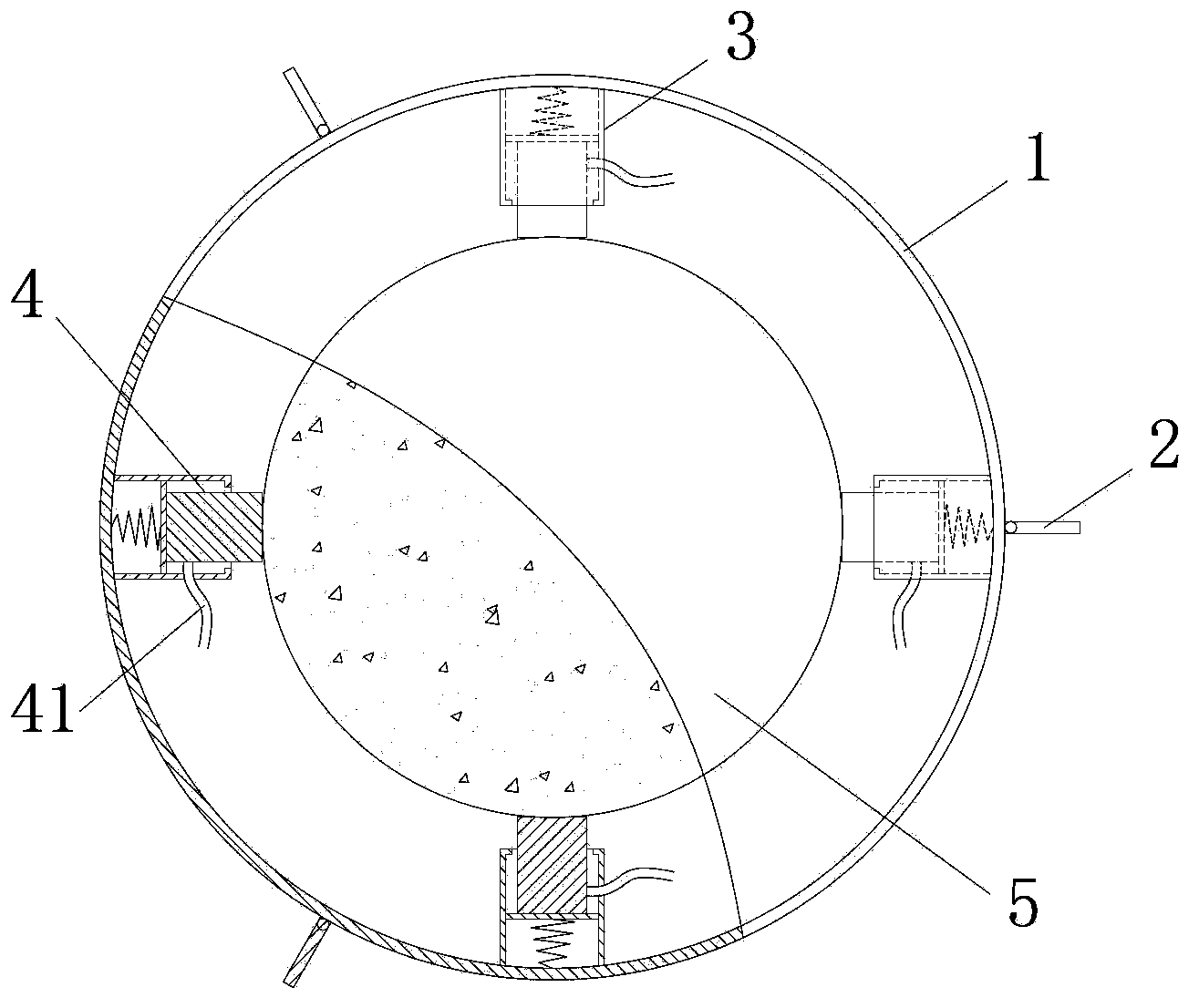
[0022] Such as figure 1 , figure 2 Shown, the round frame 1 of the sensor fixing test stand of the present invention is a cylindrical shell member, and it comprises an upper round frame 11 and a lower round frame 12, and the upper round frame 11 and the lower round frame 12 are passed through three evenly distributed tripods 2 are welded together to jointly play the role of fixing the spatial position of the abutting device 3. Two clinging devices 3 are respectively welded on the upper round frame 11 and the lower round frame 12. The said clinging devices 3 are cylindrical shells with the same shape and size, and their axes are aligned with the center line of the round frame 1. . The two close-fitting devices 3 on the same round frame are distributed symmetrically at intervals of 180 degrees, and the close-fitting devices 3 on the upper round frame 11 a...


PUM


Abstract

The invention discloses a sensor fixing test rack for a uniaxial compression sound emission test of coal petrography and an application method of the sensor fixing test rack. The test rack comprises a round rack in which a coal petrography sample is arranged, and three foot stools distributed at 120 degrees and used for fixing the round rack, wherein clinging devices used for fixing sound emission sensors in contact with the coal petrography sample are arranged on the round rack; the round rack comprises an upper round rack and a lower round rack which are respectively fixed with the upper parts and the lower parts of the three foot stools; the plurality of clinging devices are respectively fixed on the upper round rack and the lower round rack. When in use, the sensor fixing test rack is placed on a uniaxial compression tester; a coupling agent is uniformly applied on the surfaces of the signal acquisition ends of the sound emission sensors; after the sound emission sensors are mounted, the coal petrography sample is placed, and then the uniaxial compression sound emission test can be performed. The sensor fixing test rack solves the problems that at present, when the uniaxial compression sound emission test is performed in a laboratory, the spatial position of the sensors can not be fixed accurately, the sensors drop in the testing process, and high labor intensity is caused by repeated disassembly and assembly of the sensors.

Description

technical field [0001] The invention relates to a fixed sensor test frame and a use method thereof, in particular to a sensor fixed test frame suitable for coal rock uniaxial compression acoustic emission test and a use method thereof. Background technique [0002] When the laboratory conducts uniaxial compression acoustic emission tests on coal and rock materials, the acoustic emission sensor is required to be in close contact with the coal and rock samples and be able to be fixed on the surface of the samples. At present, there is no device specially used for fixing acoustic emission sensors on the surface of standard cylindrical samples such as coal and rock. The surface of the acoustic emission sensor is fixed by coating solid butter on the surface of the sensor, and then fixed with a rubber band. The problem of the sensor falling off during the process, and the acoustic emission sensor needs to be disassembled and assembled repeatedly, in this case, the loss of the samp...

Claims


Application Information

Patent Timeline
IPC IPC(8): G01N29/26G01N29/14
Inventor 李振雷窦林名何江蔡武王桂峰丁言露秦松
Owner CHINA UNIV OF MINING & TECH
Learn More