Double-drive mechanism of pumping unit

A pumping unit and dual-drive technology, which is used in the production of fluids, wellbore/well components, and earth-moving drilling, etc., can solve the problems of heavy equipment, unstable machines, limited power, etc. Good force balance and low calorific value

Active Publication Date: 2013-11-27
FUJIAN IECCO ELECTRICAL TECH
View PDF5 Cites 5 Cited by
  • Summary
  • Abstract
  • Description
  • Claims
  • Application Information

AI Technical Summary

Problems solved by technology

[0008] The purpose of the present invention is to provide a double-drive mechanism for pumping units, which overcomes the shortcomings of the existing single-drive mechanism, such as bulky equipment, limited power, and unstable machine platform.

Method used


Image

  • Double-drive mechanism of pumping unit
  • Double-drive mechanism of pumping unit
  • Double-drive mechanism of pumping unit

Examples


Embodiment Construction

[0032] The present case will be described in further detail below in conjunction with the accompanying drawings and specific embodiments.

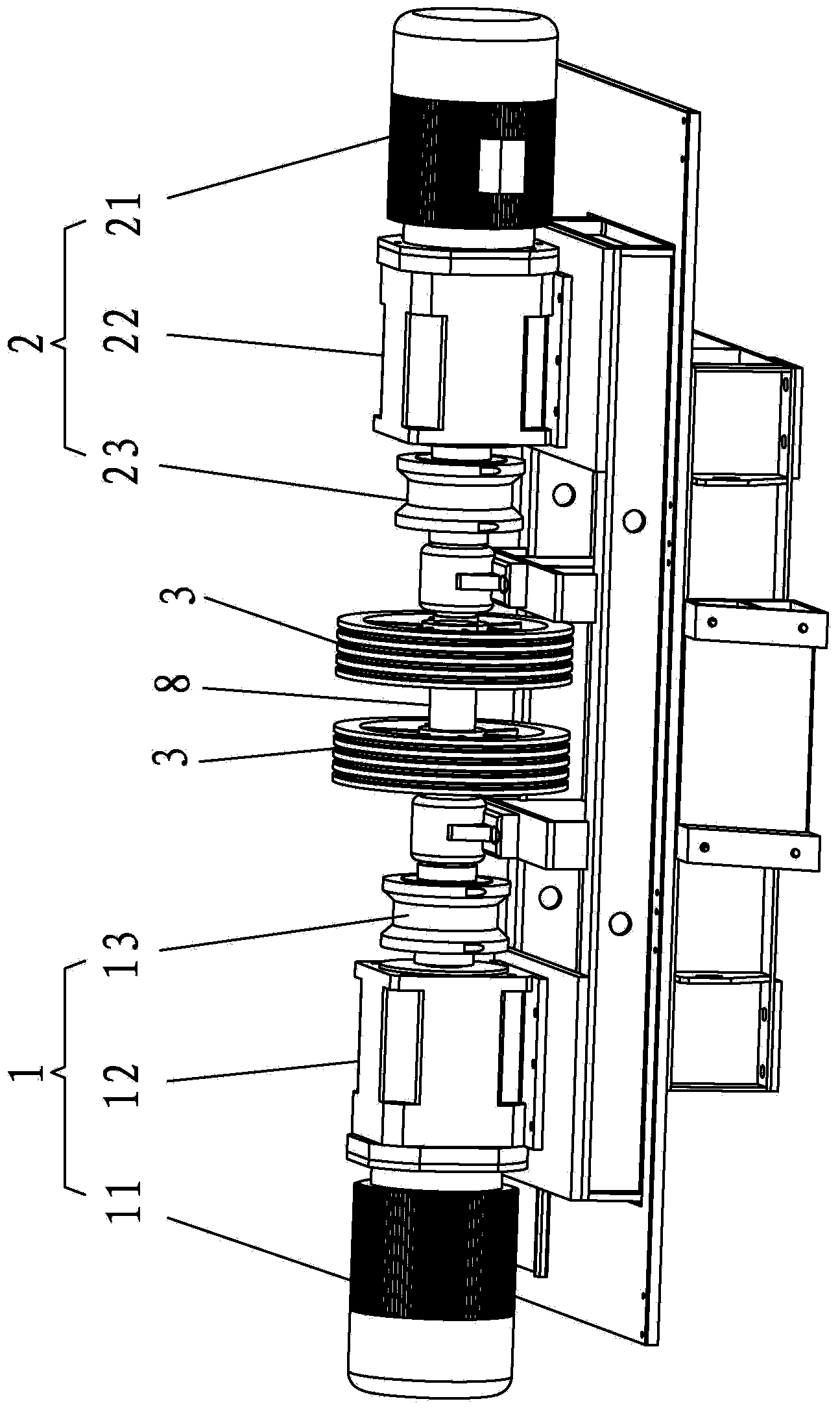
[0033] This case involves a pumping unit double drive mechanism, such as figure 1 As shown, it mainly includes a main drive group 1 and a slave drive group 2 symmetrically arranged at both ends of the main shaft. The main driving group 1 includes a main synchronous motor 11 , a reducer 12 and a shaft coupling 13 which are sequentially connected by transmission. The slave driving group 2 includes a slave synchronous motor 21 , a speed reducer 22 and a shaft coupling 23 which are sequentially connected by transmission. The coupling 13 of the main drive group 1 is connected to the output shaft of the reducer 12 and one end of the main shaft 8, and the coupling 23 of the slave drive group 2 is connected to the output shaft of the reducer 22 and one end of the main shaft 8, The main shaft 8 is sheathed with a traction sheave 3 . Preferably, ...


PUM


Abstract

The invention discloses a double-drive mechanism of a pumping unit. The mechanism comprises a main drive group and an auxiliary drive group which are arranged at two ends of a spindle symmetrically. The main drive group comprises a main synchronization motor, a reducer and a coupler which are sequentially connected in a transmission mode. The auxiliary drive group comprises an auxiliary synchronization motor, a reducer and a coupler which are sequentially connected in a transmission mode. The two couplers of the main drive group and the auxiliary drive group are connected with one end of an output shaft and one end of a spindle of corresponding reducers, and a traction sheave is sleeved on the spindle. The double-drive mechanism further comprises a synchronization control system used for controlling the main synchronization motor and the auxiliary synchronization motor to run synchronously. The load is driven by the two drive groups synchronously, and operation capability of a machine is improved greatly. The stress balance degree of the traction sheave is good, skip kinetic moment is well avoided, and stable running of the whole machine is ensured. The double-drive mechanism has the advantages of being small in synchronization motor heating quantity, high in power factor, balanced in rotation torque distribution, less in reactive loss, remarkable in energy saving effect, low in cost, convenient to install, high in safety factor and the like.

Description

technical field [0001] The invention relates to the technical field of pumping unit drives, in particular to a double drive mechanism of a pumping unit. Background technique [0002] The pumping unit is a kind of machinery and equipment for oil extraction. The traditional type of pumping unit is the beam pumping unit. Its maximum suspended electric load is not high, and the pulling load is limited. It is only suitable for low-depth oil well pumping. . Aiming at the defects of the traditional beam pumping unit, we have researched and developed a wheeled servo pumping unit. The mechanism composed of machine and coupling is used to drive the transmission. The maximum suspension point load of the single-drive pumping unit can reach 400Nm, and can pull a load of 40t. It is suitable for oil well pumping at a depth of 6000m. These parameters are far beyond the reach of the traditional beam pumping unit. [0003] Due to the development of the breadth and depth of oil production, ...

Claims


Application Information

Patent Timeline
Patent Type & Authority Applications(China)
IPC IPC(8): E21B43/00
Inventor 苏志深王华安魏剑锋
Owner FUJIAN IECCO ELECTRICAL TECH
Why Eureka
Try Eureka