
Light rail casting line

A rail and light technology, applied in casting equipment, equipment for feeding molten metal into molds, metal processing equipment, etc., can solve the problems of high labor intensity, high work risk factor, low production efficiency, etc., and reduce labor intensity , Protect personal safety, improve work efficiency

Inactive Publication Date: 2013-11-27
宁波创二代机械科技有限公司
View PDF7 Cites 2 Cited by
  • Summary
  • Abstract
  • Description
  • Claims
  • Application Information

AI Technical Summary

Problems solved by technology

[0003] In the existing technology, manual casting is used in traditional gravity casting production, especially in precision casting. The usual way is that two people work together to lift a ladle to cast the mold shell, and rely on manpower to bear the ladle and the metal in the ladle. The weight of the liquid, manual casting has the following disadvantages: 1. The labor intensity is high. Since the casting is purely relying on manpower to carry the ladle, the physical fitness of the workers is very high, which indirectly increases the difficulty of recruitment and wages, and the traditional gravity The casting production environment is harsh, and some operating temperatures are even as high as 40 degrees or more. Workers are prone to fatigue and fatigue under long-term work, resulting in low output and low production efficiency; 2. The work risk factor is high. Burns, scalds, etc. occur from time to time during the casting process; 3. The accuracy of casting is relatively poor. Due to human factors such as hand shaking or other reasons, problems such as inaccurate casting and uneven speed will increase, resulting in sand inclusions and cavities in the product Other casting quality problems

Method used


Image

  • Light rail casting line
  • Light rail casting line
  • Light rail casting line

Examples


Embodiment Construction

[0025] The following are specific embodiments of the present invention and in conjunction with the accompanying drawings, the technical solutions of the present invention are further described, but the present invention is not limited to these embodiments.

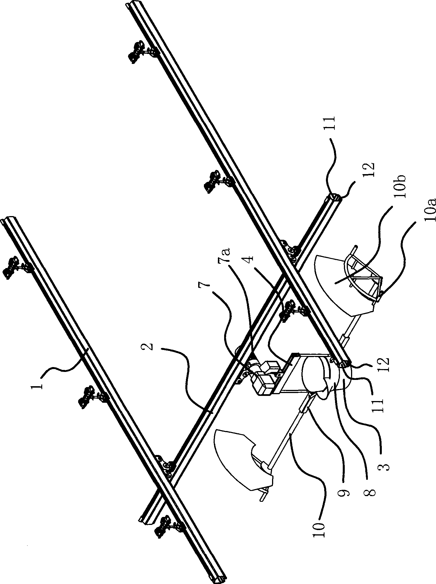
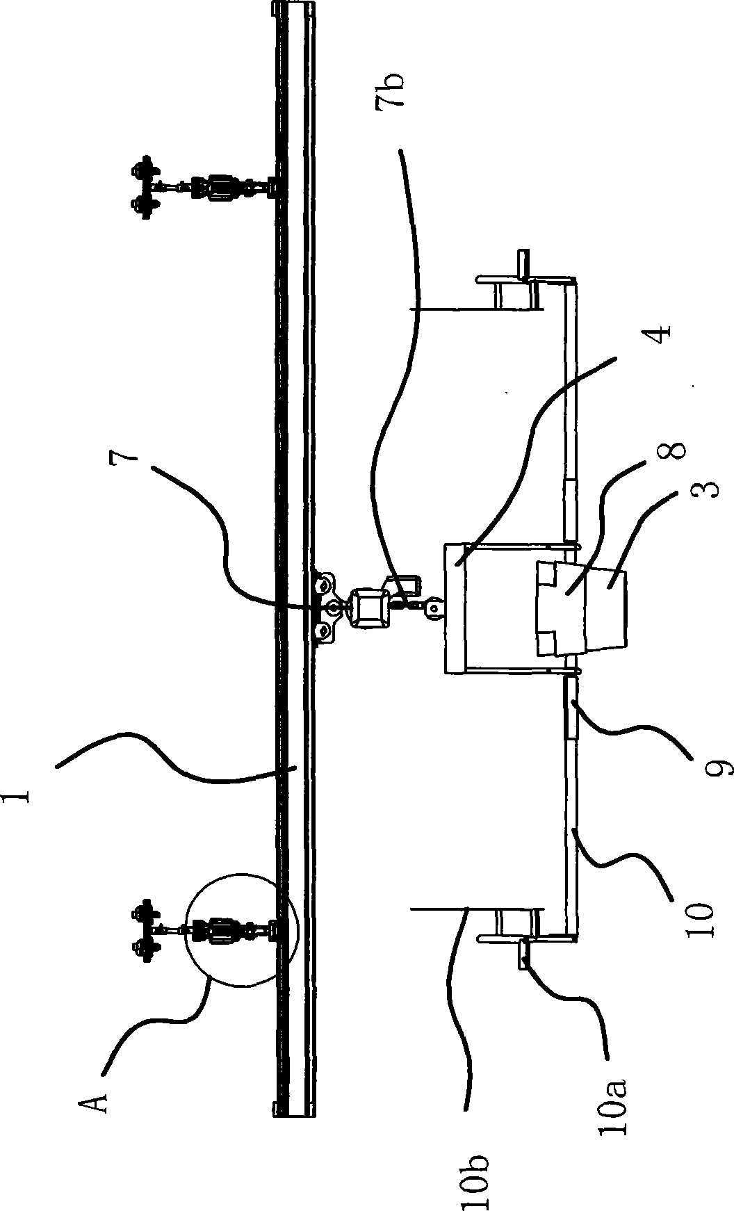
[0026] like figure 1 As shown, the light rail casting line includes a beam 2, a ladle 3, a lifting device and two horizontally parallel supporting beams 1, wherein the beam 2 and the two supporting beams 1 have a cavity 11 inside, and on one side of the beam 2 A longitudinal opening 12 communicating with the cavity 11 is provided. Similarly, a longitudinal opening 12 communicating with the cavity 11 is also provided on one side of the supporting beam 1. The supporting beam 1 is installed on the indoor roof.

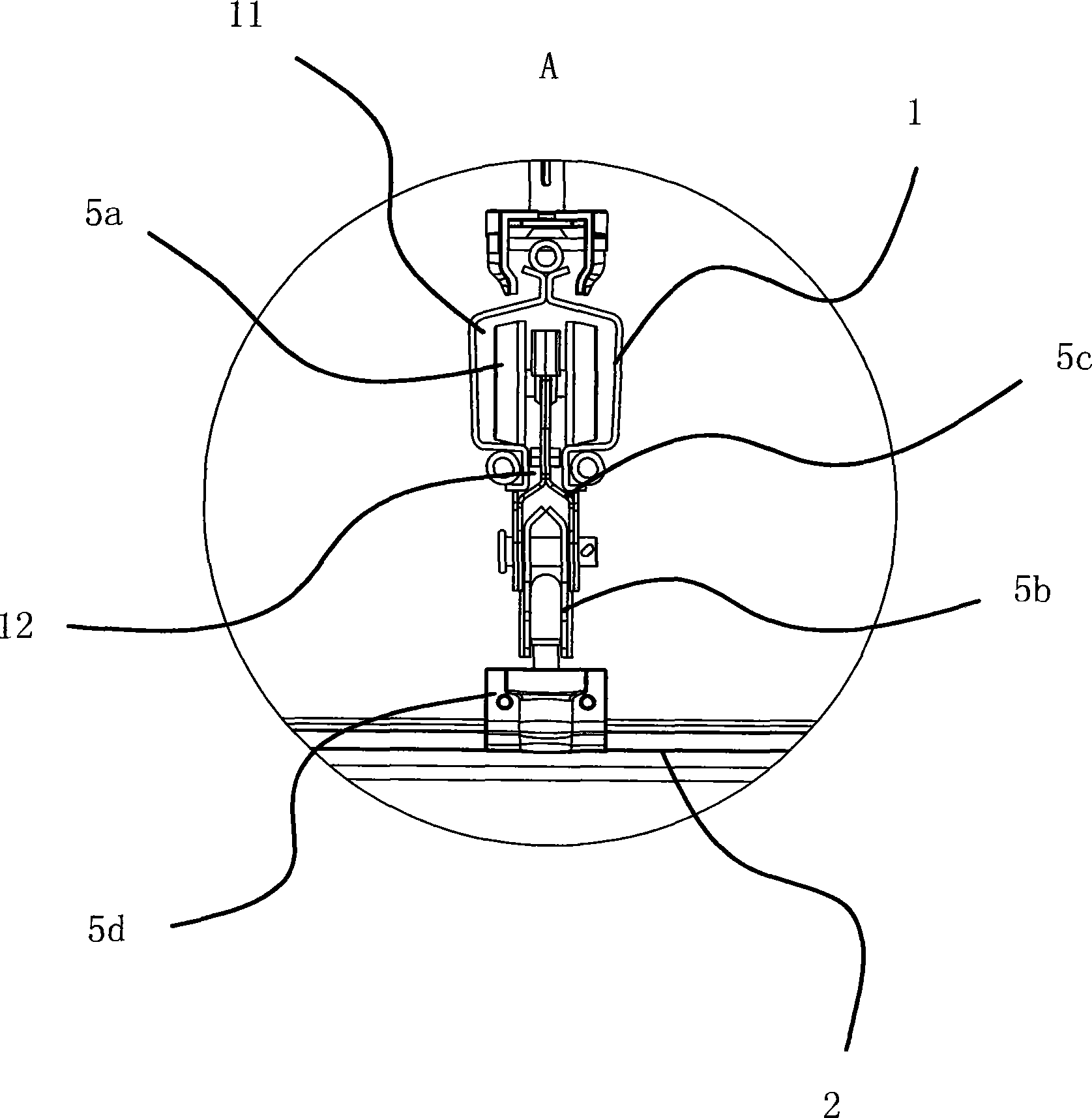
[0027] like Figure 2 to Figure 4 As shown, the crossbeam 2 and the two support beams 1 are slidingly connected by the first pulley assembly 5, the first pulley assembly 5 includes the first pulley 5a, the first conn...


PUM


Abstract

The invention provides a light rail casting line and belongs to the field of gravity casting. The light rail casting line solves the problem that casting ladles are carried manually in the casting industry so that the labor intensity is high, the risk is high, and efficiency is low. The light rail casting line comprises a beam, a casting ladle, a lifting device and two horizontally and parallelly arranged supporting beams. The beam is slidably connected between the two supporting beams, the lifting device is slidably connected on the beam, the lower portion of the lifting device is connected with a suspension frame, symmetrically arranged supporting rods are installed on two sides of the casting ladle, the casting ladle is hooked on the suspension frame through the supporting rods, and lifting rods are fixedly inserted into every supporting rod. The light rail casting line has the advantages of being low in labor intensity, good in safety and high in efficiency.

Description

technical field [0001] The invention belongs to the field of gravity casting, in particular to a light track casting line. Background technique [0002] Gravity casting refers to the process of pouring molten metal into the mold under the action of the gravity of the earth, also known as gravity casting. In a narrow sense, it mainly refers to metal mold casting. This casting method has low equipment cost and short mold shell manufacturing cycle, and is widely used in industrial production. [0003] In the existing technology, manual casting is used in traditional gravity casting production, especially in precision casting. The usual way is that two people work together to lift a ladle to cast the mold shell, and rely on manpower to bear the ladle and the metal in the ladle. The weight of the liquid, manual casting has the following disadvantages: 1. The labor intensity is high. Since the casting is purely relying on manpower to carry the ladle, the physical fitness of the w...

Claims


Application Information

Patent Timeline
Patent Type & Authority Applications(China)
IPC IPC(8): B22D35/00
Inventor 王华伟郁自春张佑囝
Owner 宁波创二代机械科技有限公司
Learn More