
Method and system for controlling an electric motor at or near stall conditions

A technology of motors and working conditions, applied in control systems, vector control systems, control drives, etc., can solve problems such as stalls

Active Publication Date: 2013-11-20
DEERE & CO
View PDF6 Cites 3 Cited by
  • Summary
  • Abstract
  • Description
  • Claims
  • Application Information

AI Technical Summary

Problems solved by technology

For example, a stall condition may be experienced if the electric motor is propelling the vehicle from a stationary position, if the vehicle is heavily loaded, if the vehicle is pulling a trailer or implement, or if the vehicle is climbing an incline

Method used


Image

  • Method and system for controlling an electric motor at or near stall conditions
  • Method and system for controlling an electric motor at or near stall conditions
  • Method and system for controlling an electric motor at or near stall conditions

Examples


Embodiment Construction

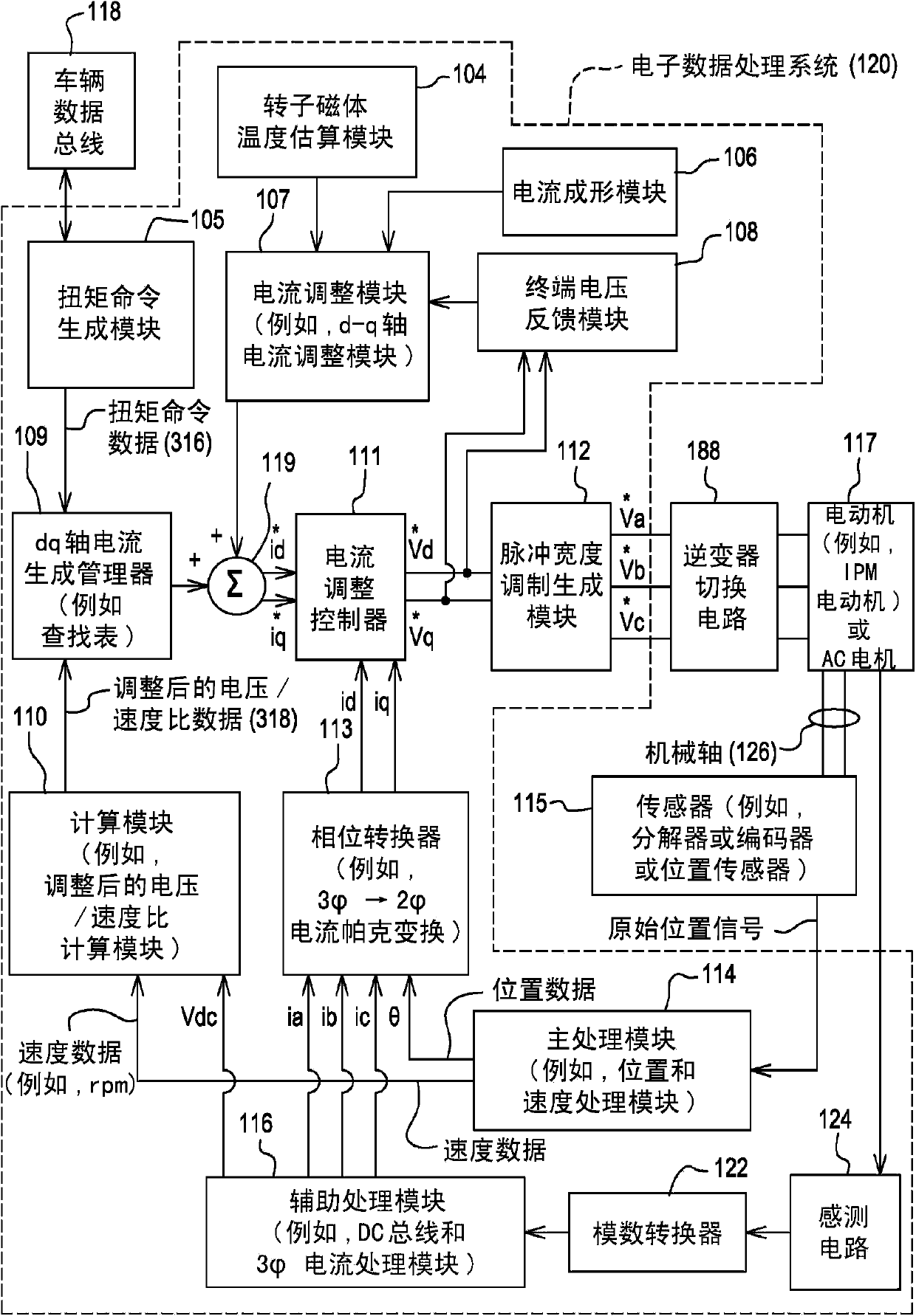
[0012] According to one embodiment, figure 1 A system for controlling an electric motor 117 (eg, an interior permanent magnet (IPM) motor) or other AC electric machine is disclosed. The methods and systems described herein can be equally applied to interior permanent magnet motors, induction motors, or surface mounted permanent magnet (PM) motors having a wide range of operating speeds. In one embodiment, other than the motor 117, the system may be referred to as an inverter or motor controller. The system or inverter is well suited to widely varying operating speeds of the motor shaft, so that a balanced or optimal pulse width modulation frequency can be selected for the inverter over one or more different speed ranges .

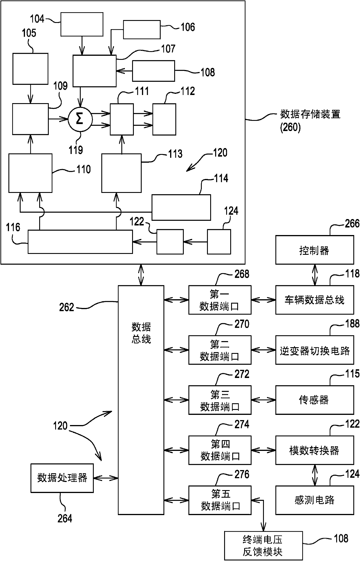
[0013] The system includes electronic modules, software modules, or both. In one embodiment, the motor controller includes an electronic data processing system 120 to support the storage, processing, or execution of software instructions for one or more ...


PUM


Abstract

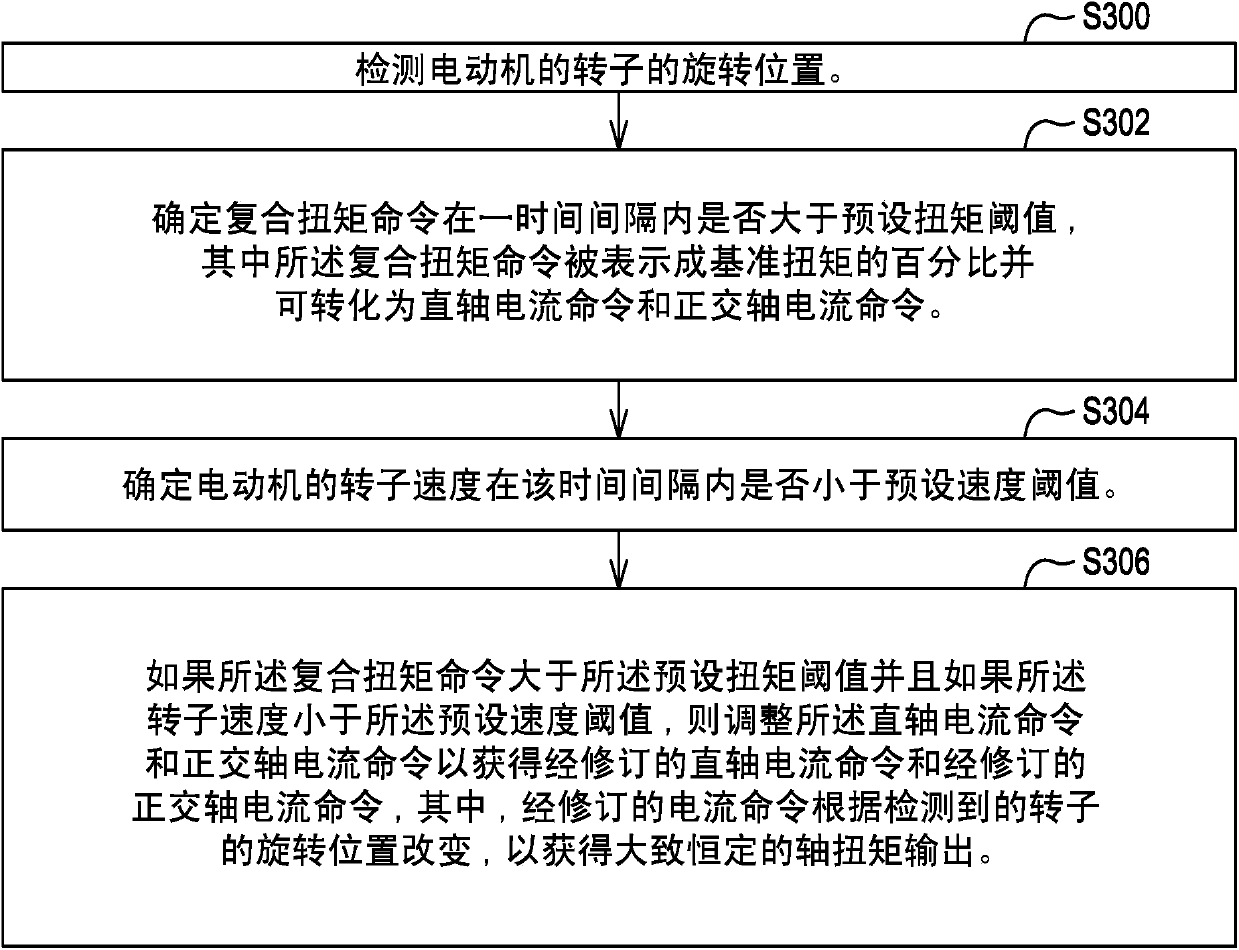
A data processor determines whether a composite torque command is larger than a preset torque threshold for a time interval. The composite torque command is convertible into a direct-axis current command and a quadrature-axis current command. The data processor determines whether a rotor speed of the motor is less than a preset speed threshold for the time interval. The data processor, the current adjustment module, or the current shaping module adjusts the direct-axis current command and the quadrature-axis current command to obtain a revised direct-axis current command and revised quadrature-axis current command for the time interval if the composite torque command is larger than the preset torque threshold and if the rotor speed is less than the preset speed threshold, where the revised current commands vary by the detected rotational position of the rotor to achieve a generally constant shaft torque output.

Description

[0001] The present invention is based on the requirements of 35U.S.C.119(e) based on the filed on February 28, 2011, entitled "METHOD AND SYSTEM FOR CONTROLLING AN ELECTRIC MOTOR AT OR NEAR STALL CONDITIONS)" U.S. Provisional Application No. 61 / 447,323. technical field [0002] The present invention relates to methods and systems for controlling electric motors at or near stall conditions. Background technique [0003] Electric motors are characterized by rotors and stators with permanent magnets, eg, interior permanent magnet (IPM) motors, IPM synchronous motors, surface mounted permanent magnet motors, or other permanent magnet motor configurations. Electric motors can be used to propel a vehicle, and vehicle propulsion typically requires control over a wide range of motor speeds. [0004] A stall condition is when a torque load is applied to the motor causing the shaft speed of the motor to become at or near zero rpm. For example, a stall condition may be experienced if...

Claims


Application Information

Patent Timeline
Patent Type & Authority Applications(China)
IPC IPC(8): B60K1/00
CPCH02P21/04H02P29/50B60L2240/529Y02T10/72B60L2240/425B60L15/2045B60L2240/421B60L2240/423Y02T10/64
Inventor 吴隆罗伯特·肖
Owner DEERE & CO
Learn More