
Web member intersecting and split joint connector structure in positions of steel truss girder bridge nodes

A steel truss bridge and crossover technology, applied in truss bridges, bridges, bridge forms, etc., can solve the problems of welding fatigue, excessive stress concentration, etc., and achieve the effect of saving steel, reducing size, and achieving remarkable effects.

Active Publication Date: 2013-11-20
CHINA MAJOR BRIDGE ENERGINEERING
View PDF7 Cites 3 Cited by
  • Summary
  • Abstract
  • Description
  • Claims
  • Application Information

AI Technical Summary

Problems solved by technology

[0003] The purpose of the present invention is to aim at the above-mentioned present situation, aiming to provide a steel truss girder which can solve the problems of excessive stress concentration and welding fatigue caused by the cross welding of web joint plates, and can reduce the size of the gusset plate and save steel materials The cross-jointed joint structure of the web members at the bridge nodes

Method used


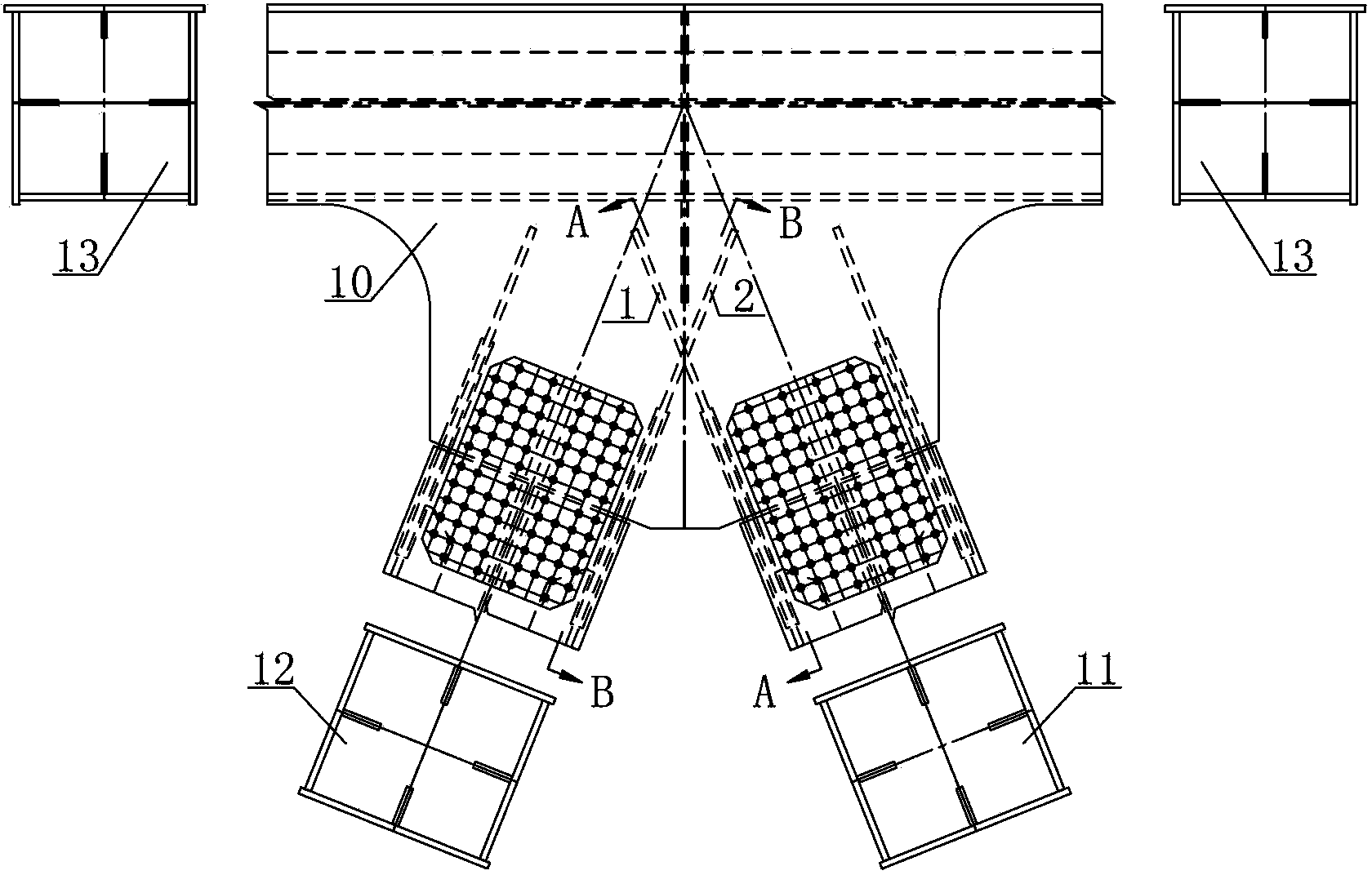
Image

  • Web member intersecting and split joint connector structure in positions of steel truss girder bridge nodes
  • Web member intersecting and split joint connector structure in positions of steel truss girder bridge nodes
  • Web member intersecting and split joint connector structure in positions of steel truss girder bridge nodes

Examples


Embodiment Construction

[0014] Specific embodiments of the present invention will be described in detail below in conjunction with the accompanying drawings.

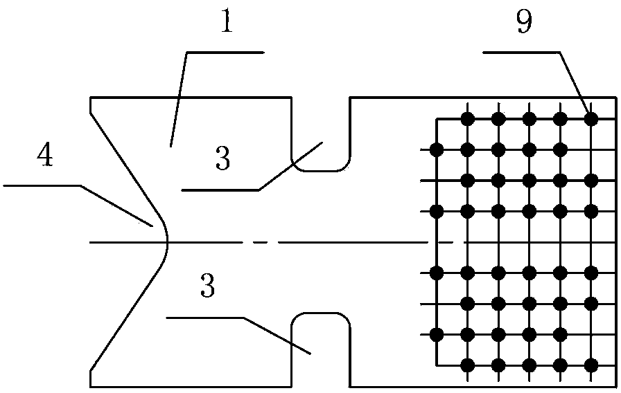
[0015] refer to figure 1 , There are U-shaped grooves-3 on both sides of the splicing joint plate-1 of the present invention, a dovetail groove 4 at the tail, and high-strength bolt holes at the end.

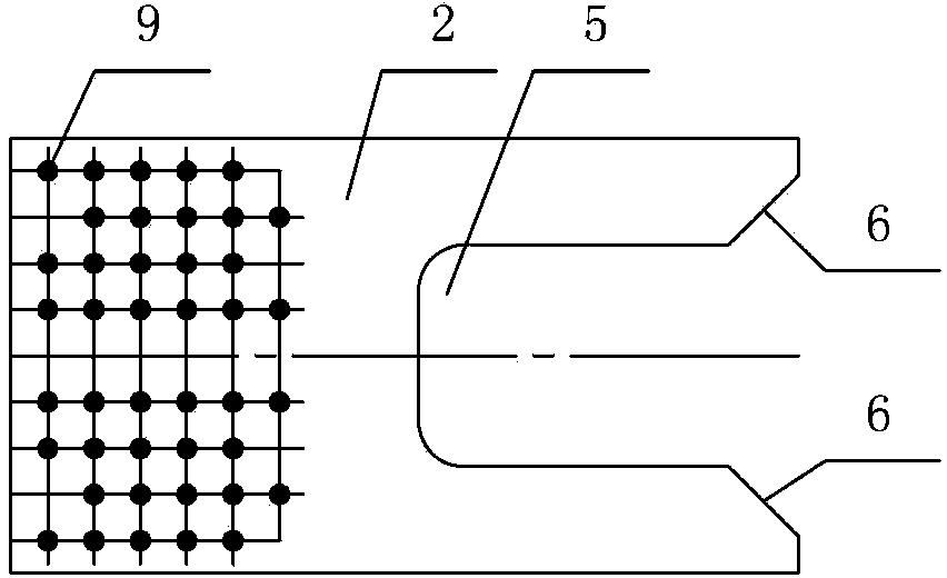
[0016] refer to figure 2 , There is a U-shaped groove 2 5 in the middle of the splicing joint plate 2 2 tail, the tail has a chamfer 6, and the end has a high-strength bolt hole.

[0017] refer to figure 2 , 3 , 4, 5, the middle section of the U-shaped groove-3 notch of joint plate 1 passes through the U-shaped groove 2 of joint plate 2, and the space of the two spliced ​​joint plates intersects and staggers each other. The two ends of the plate are welded to the gusset plate 10 at the node of the steel truss girder, and there is a weld 7 at the weld. The gusset plate 10 is welded to the chord 13 .

[0018] The joint plate 1 is bolted to...


PUM


Abstract

The invention relates to a web member intersecting and split joint connector structure in the positions of steel truss girder bridge nodes. The middle section of a groove opening of a first U-type groove of a first connector plate penetrates through a second U-type groove of a second connector plate, the space of the first connector plate and the space of the second connector plate intersect and are staggered, the connector plates are welded with node plates in the position of the steel truss girder bridge nodes, and the node plates are welded with chord members; then the connector plates are in bolt joint connection with the member ends of web members through split joint plates and high-strength bolts to form an integrated structure and jointly bear force. Because the intersecting split joint connector plates are welded to the node plates after being mutually staggered in space, and are then in bolt joint connection with the member ends of the web members through the split joint plates and the high-strength bolts to form the integrated structure and jointly bear force, the force can be reasonably borne. The web member intersecting and split joint connector structure in the positions of the steel truss girder bridge nodes can avoid the problems of excessively centralized stress and welding fatigue which are caused by direct intersecting and welding of web member connector plates, can reduce sizes of the node plates and save steel materials, and is obvious in large-internal-force and large-size web member end split joint effect.

Description

technical field [0001] The invention relates to a joint structure of cross-jointed web members at the nodes of steel truss girder bridges, which is mainly used for splicing the ends of web members (slanting bars or vertical bars) at the nodes of steel truss girder bridges. Background technique [0002] For the splicing of web members at the joints of steel truss girder bridges, when the internal force is small, the size of the web members is small, and the size of the gusset plates and splicing joints required are small. Generally, plug-in splicing or ordinary pair splicing is adopted can meet the requirements. However, for steel truss girders with large spans, heavy loads, and large volumes, the joints of box-shaped webs with large internal forces and large sizes can only be spliced ​​at joints (four-sided equal-strength splicing). Weld the joint plate on the gusset plate at the node, and then splice it with the end of the web (4-sided equal-strength splicing). Due to the...

Claims


Application Information

Patent Timeline
IPC IPC(8): E01D6/00
Inventor 宁伯伟高宗余黄燕庆胡辉跃李华云刘俊锋刘承虞
Owner CHINA MAJOR BRIDGE ENERGINEERING
Learn More