
A multi-light-emitting LED lamp with a lamp cup structure

A technology of LED lamps and LED strips, applied in the field of lighting, can solve the problems of light waste on the side of LED lamps, low light transmittance, large light loss of LED chips, etc., so as to improve light loss, improve light emission, and reduce light The effect of damage

Active Publication Date: 2016-01-20
北京和竑炅源照明技术有限公司
View PDF7 Cites 0 Cited by
  • Summary
  • Abstract
  • Description
  • Claims
  • Application Information

AI Technical Summary

Problems solved by technology

When the LED chip emits light, the real effective lighting area is a part of the area directly below the light emitting direction. Obviously, the light on the side of the LED lamp is wasted
However, there are still problems even if the light-transmitting flat mirror is used for corresponding improvement. For example, the light transmittance of the general light-transmitting flat mirror is often higher than 80%, but in order to weaken the glare effect of the light passing through the lampshade, a transparent A lampshade with a low light rate, such as a lampshade with a light transmittance of about 70%, can offset part of the light intensity through the lampshade to obtain a soft light effect
But in this way, it will cause a large light loss to the LED chip.

Method used

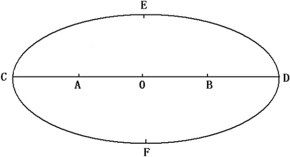
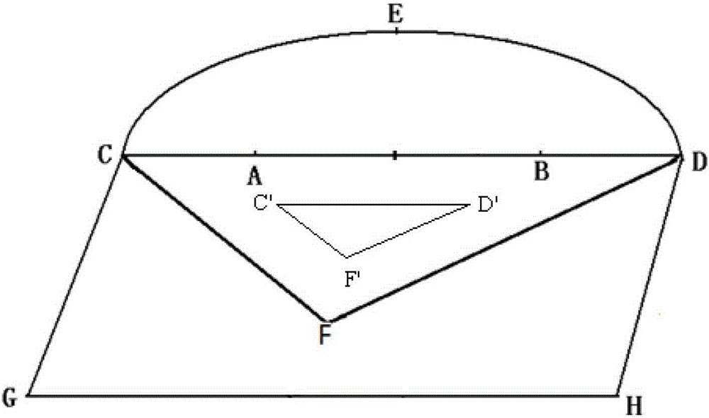

Image

  • A multi-light-emitting LED lamp with a lamp cup structure
  • A multi-light-emitting LED lamp with a lamp cup structure
  • A multi-light-emitting LED lamp with a lamp cup structure

Examples


Embodiment 1

[0030] Such as figure 2 , 3 shown, in order to solve figure 1 Problems arising in the prior art, the present application provides a multi-luminous LED lamp with a lamp cup structure, including: a substrate with an integrally formed lamp cup structure (structure composed of GCDH), at least two groups of LED lamps Belt, a reflective element for increasing light reflection efficiency, wherein, the lamp cup structure has a cup top opening (the position of GH) and a cup bottom substrate (position between points C and D), and a cross-section of the cup bottom substrate Have triangular or V-shaped protrusions.

[0031] According to the above, the specific design of the application is as follows:

[0032] The LED light strips are respectively installed on the two sides of the protrusion (the position of CF and the position of FD), thereby forming two light-emitting surfaces in the structure of the lamp cup (that is, the surface formed by point CF and the surface formed by point DF...

Embodiment 2

[0041] combine figure 2 , 3 , further comprising: a lampshade installed on the cup top opening and suspended above the LED light strip (installed at the position of GH), the distance between the cup top opening and the protrusion is greater than a threshold.

[0042] The distance between the cup top opening GH and point F is greater than a threshold. This distance can make the average light intensity irradiated on the lampshade weaker, so that the lampshade with higher light transmittance can be used without glare, and the transmittance of the lampshade The increase in light efficiency also effectively reduces the light loss of the LED chip light strip.

Embodiment 3

[0044] Such as figure 2 , the included angles formed between the cup walls of the lamp cup structure and the cup bottom substrate are greater than 90 degrees, and the area of ​​the cup top opening is larger than the area of ​​the cup bottom.

[0045] or,

[0046] Such as image 3 As shown, the angle formed by one side of the lamp cup structure and the cup bottom substrate is greater than 90 degrees, and the angle formed by the opposite cup wall of the one side cup wall and the cup bottom substrate is less than or equal to 90 degrees, the cup wall on one side and the cup wall on the opposite side are arranged asymmetrically in a batwing shape to form directional light output (that is, along the extension direction of CG and DH).

[0047] Through the above two preferred settings of the included angles formed between the cup walls of the lamp cup structure and the cup bottom substrate, it is possible to control the directional light output of the lamp.


PUM


Abstract

The invention provides a multi-light emergent surface LED (Light Emitting Diode) lamp with a lamp cup structure, comprising a substrate, at least two groups of LED lamp bands and a light reflecting element which is used for increasing the light reflecting efficiency, wherein the substrate is of the lamp cup structure which is subjected to integrated moulding; the lamp cup structure is provided with a cup top opening and a cup bottom substrate; the section of the cup bottom substrate is provided with a triangular or V-shaped bulge; the LED lamp bands are respectively arranged on the two side faces of the bulge; two light emergent surfaces are formed in the lamp cup structure; the cup wall of the lamp cup structure is provided with a movable fixing structure; the light reflecting element is movably inserted into the cup wall through the movable fixing structure; another part of light rays emitted by each light emergent surface is directly emitted from the cup top opening. By using the multi-light emergent surface LED lamp, the light loss degree of a light source is effectively improved, adjustment can be carried out according to different needs of light emergence, and light emergence can be optimally realized.

Description

technical field [0001] The present application relates to the lighting field, in particular to an LED lamp with multiple light-emitting surfaces and a lamp cup structure. Background technique [0002] In the existing LED lamps, a lampshade is installed above the chip in the aluminum substrate, and a radiator is installed on the opposite side of the chip, that is, the other side of the aluminum substrate. When the LED chip emits light, the real effective lighting area is a part of the area directly below the light emitting direction. Obviously, the light on the side of the LED lamp is wasted. However, there are still problems even if the light-transmitting flat mirror is used for corresponding improvement. For example, the light transmittance of the general light-transmitting flat mirror is often higher than 80%, but in order to weaken the glare effect of the light passing through the lampshade, a transparent A lampshade with a low light rate, such as a lampshade with a ligh...

Claims


Application Information

Patent Timeline
Patent Type & Authority Patents(China)
IPC IPC(8): F21S4/00F21V7/10F21V17/10F21V23/06F21Y101/02F21Y115/10
Inventor 李忠凯
Owner 北京和竑炅源照明技术有限公司
Learn More