
Rotational flow dehydration and medium removing machine

A technology of cyclone dehydration and de-intermediation machine, which is applied in cyclone devices, devices whose axial directions of cyclone can be reversed, solid separation, etc. Difficulty and maintenance time, increase maintenance costs and other issues, to achieve the effect of saving required space, sufficient pulp separation, and increasing liquid flow rate

Inactive Publication Date: 2013-11-13
TSINGHUA UNIV +1
View PDF6 Cites 3 Cited by
  • Summary
  • Abstract
  • Description
  • Claims
  • Application Information

AI Technical Summary

Problems solved by technology

[0006] Severe body wear: Although all wear-resistant ceramics are used inside the dense medium cyclone, the wear is still serious in the cone angle concentration stage. The wear-resistant materials in this part need to be replaced every two weeks, which not only improves maintenance Cost, but also increases the difficulty and time of maintenance
[0007] Insufficient processing capacity: Usually, one dense medium cyclone is difficult to support the production of the entire mining area, especially for large-scale concentrators, which require two or more cyclones to operate simultaneously to meet the demand
[0013] Comprehensive energy consumption: At present, the dual-motor system of the linear vibrating screen for dehydration and de-intermediation has high energy consumption, and two motors need to be used to drive the entire screen surface to move

Method used


Image

  • Rotational flow dehydration and medium removing machine
  • Rotational flow dehydration and medium removing machine
  • Rotational flow dehydration and medium removing machine

Examples


Embodiment Construction

[0032] The present invention provides a cyclone dehydration and deintermediation machine, and the present invention will be further described below in conjunction with the accompanying drawings and specific embodiments.

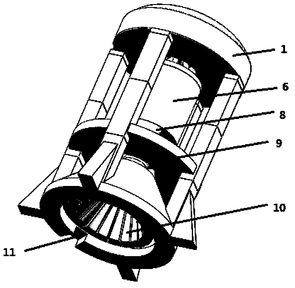
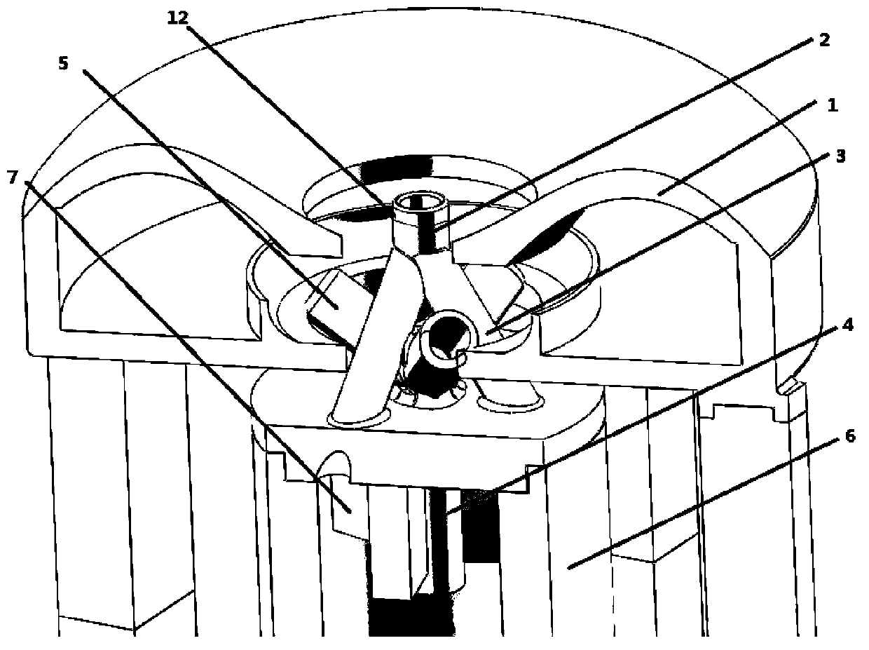
[0033] The structure of the present invention is as figure 1 As shown, the entire cyclone dehydration and deintermediation machine is fixed by the frame. The lower end of the cyclone cylinder 6 is connected to the cyclone cone 8 to form a cyclone together, and an overflow weir 1 is arranged above the cyclone cylinder 6 . The main body of the cyclone dehydration and deintermediation machine is composed of a cyclone rotated by the cylinder and a horn-shaped screen body 10 mechanically connected to it. The upper part can play the role of sorting the cyclone; the lower part can play the role of The role of dehydration and sieve. The barrel of the entire cyclone rotates together with the feed pipe.

[0034] The slurry in the cyclone part is fed by a centrifugal...


PUM


Abstract

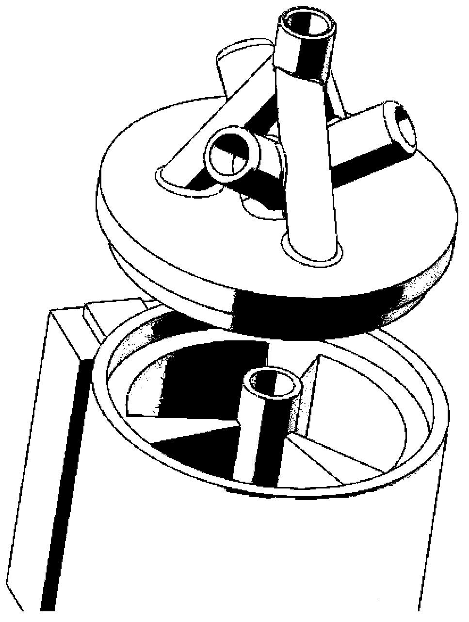
The invention belongs to the field of rotational flow equipment, and particularly relates to a rotational flow dehydration and medium removing machine for classifying particle sizes and densities in a mineral processing field. The dehydration and medium removing machine is characterized in that an overflow weir is arranged above a barrel of a rotational flow device, the lower end of the barrel of a rotational flow device is connected with a cone of the rotational flow device, the lower end of the cone of the rotational flow device is provided with a sieve body, and an upper end cover of the barrel of the rotational flow device is provided with a material feeding pipeline and an overflow pipeline; the material feeding pipeline is composed of a main pipeline and n branch pipelines, each branch pipeline and the main pipeline are communicated in a certain angle, and the branch pipelines are uniformly distributed below the main pipeline at equal intervals and angles; the structure of the overflow pipeline is the same as that of the material inlet pipeline, the whole pipe body is reversely arranged, a main pipeline of the overflow pipeline stretches into the barrel of the rotational flow device; the branch pipelines of the overflow pipeline stretches into the overflow weir, and n flow stabilizing plates which are uniformly distributed are arranged between the inner wall of the rotational flow device barrel and the main pipeline of the overflow pipeline. The dehydration and medium removing machine provided by the invention has the advantages that materials and the barrel can rotate together, abrasion is reduced, the revolving speed is increased, the handling capacity is increased, and the sieve device arranged on the lower part of the dehydration and medium removing machine can play the dehydration and medium removing role.

Description

technical field [0001] The invention belongs to the field of cyclone equipment, in particular to a cyclone dehydration and de-intermediation machine used for particle size and density classification in the field of mineral processing. Background technique [0002] Among the currently used mineral processing equipment, dense medium cyclones are very mature and widely used, and have been widely used all over the world. The dehydration and mediation removal equipment is mainly based on the common separation of curved screens and linear vibrating screens. The world's proven coal reserves are close to one trillion tons, so the potential for mineral processing is very large. [0003] In 1945, the Netherlands State Coal Mine proposed the method of separating fine coal with a dense medium cyclone, and created the DSM dense medium cyclone. This kind of high-efficiency mineral processing equipment that uses centrifugal force to strengthen the gravity separation process has gradually...

Claims


Application Information

Patent Timeline
IPC IPC(8): B04C5/26B04C5/02B04C5/12B07B1/00
Inventor 朱明瞿体明郑水林王新文
Owner TSINGHUA UNIV
Learn More