
Plate lock

A blade lock and blade technology, which is used in construction locks, cylinder pin locks, locks with turning keys, etc., can solve the problem of high mutual opening rate

Inactive Publication Date: 2013-11-06
骆国基
View PDF7 Cites 3 Cited by
  • Summary
  • Abstract
  • Description
  • Claims
  • Application Information

AI Technical Summary

Problems solved by technology

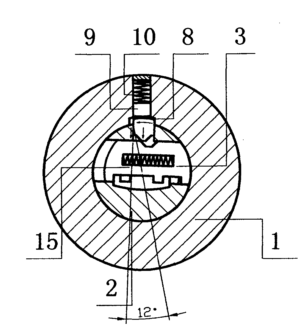
[0002] The patent No. ZL 200720062590.6 is a patent titled "An Anti-theft Leaf Lock and Key". Its structure and principle are that there are Shaped grooves, through these grooves to control the locking pin to lock and open, its anti-technical opening performance has been improved to a certain extent, but it has three disadvantages, first, the mutual opening rate is high, and the use of tooth marks If the similar key is inserted, it is possible to open the lock. For example, take two keys with a tooth pattern of 123456 and a tooth pattern of 223456 as an example. The former is a matching key, and the latter is a key with similar tooth patterns. The flowers are exactly the same, only the first bit is different, and the difference between their first teeth 1 and 2 is very small. When a key with similar teeth is inserted into the lock cylinder, the last 5 blades in the lock cylinder The shaped grooves have been aligned, only the first The shaped groove is slightly deviated from the straight line, and the inner end of the locking pin has mostly entered the back 5 pages. shaped groove, with only one end resting on the first sheet of the On the hypotenuse of the shaped groove, the outer end of the locking pin basically retreats from the lock body into the lock cylinder, and only one end corresponding to the first blade still remains in the lock body, which is in a semi-open state (see figure 1 ), at this moment the key can be opened by twisting the key a little harder; secondly, there are still conditions for technical opening. Groove coincides, convex The left and right sides are straight sides parallel to the center line, and these straight sides form a certain angle with the center of the lock cylinder (see figure 1 ), when the technology is opened, twist the lock cylinder, the lock pin will bear against the lock groove of the lock body, and the lock groove will produce a reaction force on the lock pin, at this time, the angle formed by the lock pin and the center of the lock cylinder will cause the lock pin The reaction force part is converted into centripetal force, and the centripetal force makes the locking pin press the leaf, and the leaf is moved. The groove is dialed under the locking pin, and the centripetal force makes the locking pin enter the thirdly, the anti-violent opening performance is not strong enough, the above-mentioned patent relies on the one-way locking of the locking pin, when the lock cylinder is inserted and twisted by a high-strength unlocking tool, the locking pin may was twisted, causing the lock to be violently opened

Method used


Image

  • Plate lock
  • Plate lock
  • Plate lock

Examples


Embodiment Construction

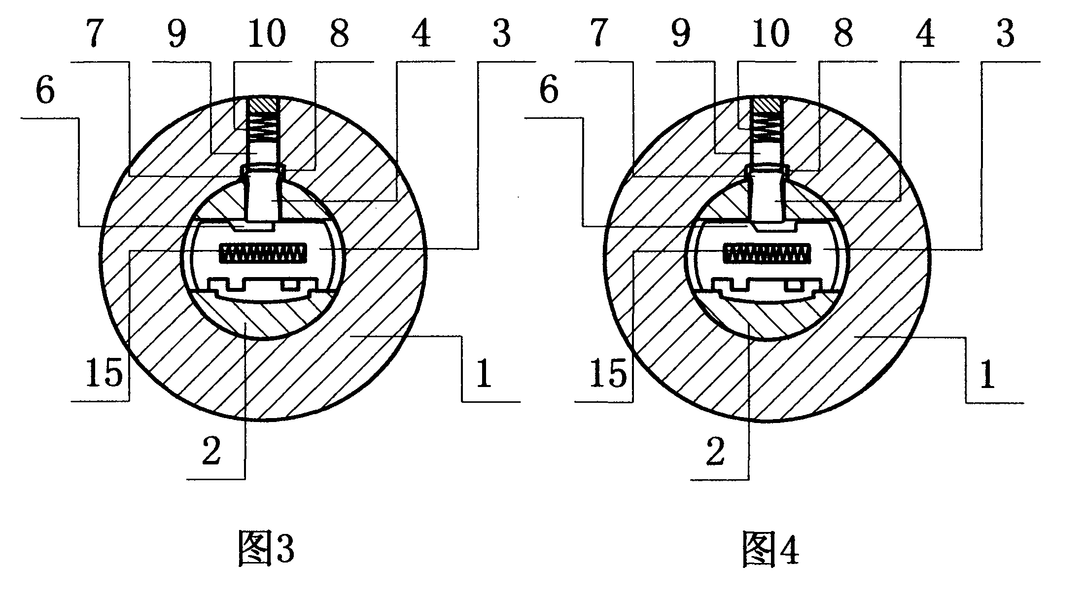
[0021] Figure 5 , Figure 6 Shown is the first embodiment of the present invention, including lock body 1, lock core 2, leaf 3, Shaped locking pin 4, the lock core 2 is sleeved in the lock body 1, and the lock core 2 is provided with several groups of leaf sheets 3 stacked in front and back as a group, and the middle part of the leaf sheet 3 is provided with a return spring 15. There are 3 pieces One side of the groove 6 pushed by the spring 15 is set as a vertical side, and the side pushed by the key tooth flower is set as a hypotenuse; the lock core 2 corresponds to the leaf 3 Shaped groove 6 places are provided with Form locking pin 4, Two sides 7 of the outer end of shape locking pin 4, the included angle with the center of circle of lock core respectively is 0 °, and corresponding to lock body 1 There is a locking groove 8 at the shape locking pin, and a flat ball 9 and a return spring 10 are provided.

[0022] When opening, when the matching key is inserted ...


PUM


Abstract

A plate lock comprises a lock body, a lock cylinder and a plate and is characterized in that the lock cylinder is mounted inside the lock body in a sleeved manner, a plurality groups of plate, with two overlapped plates as a group, are arranged on the lock cylinder, grooves are formed in the plate, a tangible locking pin is arranged on the lock cylinder corresponding to the plate-shaped groove, a locking groove is formed in the lock body corresponding to tangible locking pin, a spring free left and right locked plate is additionally arranged between each two groups of overlapped plates, a left locking groove and a right locking groove are formed in the lock body corresponding to the spring free left and right locked plate, under the state of shutting, the outer end of the tangible locking pin enters the locking groove of the lock body, the left end and the right end of the spring free left and right locked plate enter the left locking groove and the right locking groove, so as to form two direction locking or three direction locking, and enhance the performance of anti-violent opening.

Description

technical field [0001] The present invention relates to a kind of lock, more particularly, it relates to a kind of leaf lock head. Background technique [0002] The patent No. ZL 200720062590.6 is a patent titled "An Anti-theft Leaf Lock and Key". Its structure and principle are that there are Shaped grooves, through these grooves to control the locking pin to lock and open, its anti-technical opening performance has been improved to a certain extent, but it has three disadvantages, first, the mutual opening rate is high, and the use of tooth marks If the similar key is inserted, it is possible to open the lock. For example, take two keys with a tooth pattern of 123456 and a tooth pattern of 223456 as an example. The former is a matching key, and the latter is a key with similar tooth patterns. The flowers are exactly the same, only the first bit is different, and the difference between their first teeth 1 and 2 is very small. When a key with similar teeth is inserted into...

Claims


Application Information

Patent Timeline
Patent Type & Authority Applications(China)
IPC IPC(8): E05B29/00E05B15/00E05B15/14E05B15/04
Inventor 骆国基
Owner 骆国基
Learn More