
Looking-around synthetic aperture imaging radar

An imaging radar and synthetic aperture technology, applied in the field of ship navigation, can solve the problems of high transmit power, difficulty, interference, etc., achieve high azimuth and direction resolution, ensure ship safety, and improve the effect of detection performance

Inactive Publication Date: 2013-10-23
WUHAN UNIV
View PDF9 Cites 11 Cited by
  • Summary
  • Abstract
  • Description
  • Claims
  • Application Information

AI Technical Summary

Problems solved by technology

[0002] Traditional ship navigation devices (such as ship-borne X / S-band navigation radar) use pulse system radar to monitor targets around the ship. This type of navigation device has the following disadvantages: 1. Due to the limitation of time-bandwidth product, if the distance resolution is high , the operating distance becomes smaller, and if the operating distance is large, the distance resolution becomes poor; 2. It belongs to the real aperture radar, and its azimuth resolution is limited by the antenna aperture, which is difficult to be further improved; 3. Magnetron emission technology is often used , is a non-coherent radar, which often requires higher transmission power and is prone to electromagnetic interference; 4. It is easily interfered by other radars working in the same frequency band; 5. There is a large (hundreds of meters) short-range blind zone; 6. It cannot directly Detect target speed; 7. Do not have the ability to obtain dynamic parameters of the ocean around the ship while navigating

Method used


Image

  • Looking-around synthetic aperture imaging radar
  • Looking-around synthetic aperture imaging radar
  • Looking-around synthetic aperture imaging radar

Examples


Embodiment Construction

[0026] One, below in conjunction with accompanying drawing, the present invention will be further described.

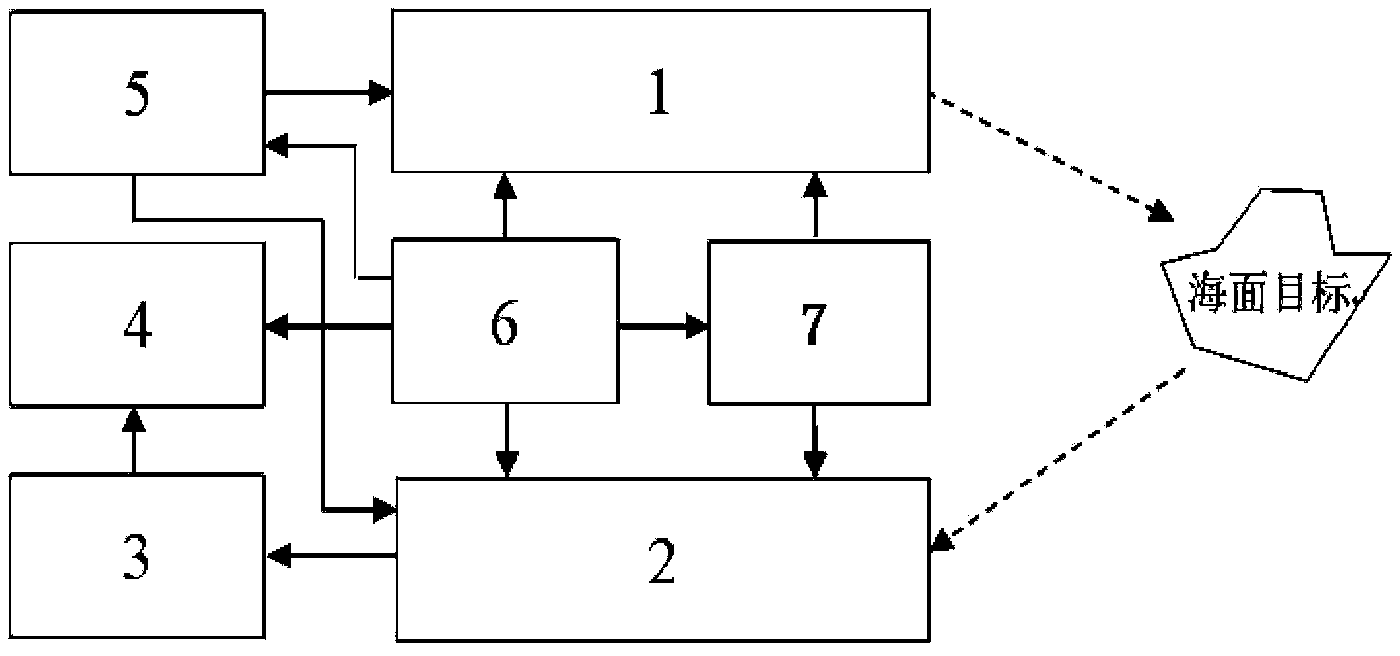
[0027] see figure 1 , the present invention includes a transmitting unit 1, a receiving, amplifying, down-converting and filtering unit 2, a signal processing and imaging unit 3, a display unit 4, a radio frequency signal generating unit 5, a control unit 6, and a power unit 7 for controlling the rotation of the transmitting and receiving antenna;

[0028] The control unit 6 is respectively connected with the transmitting unit 1, the receiving, amplifying, down-converting and filtering unit 2, the display unit 4, the radio frequency signal generating unit 5, and the power unit 7 for controlling the rotation of the transmitting and receiving antenna;

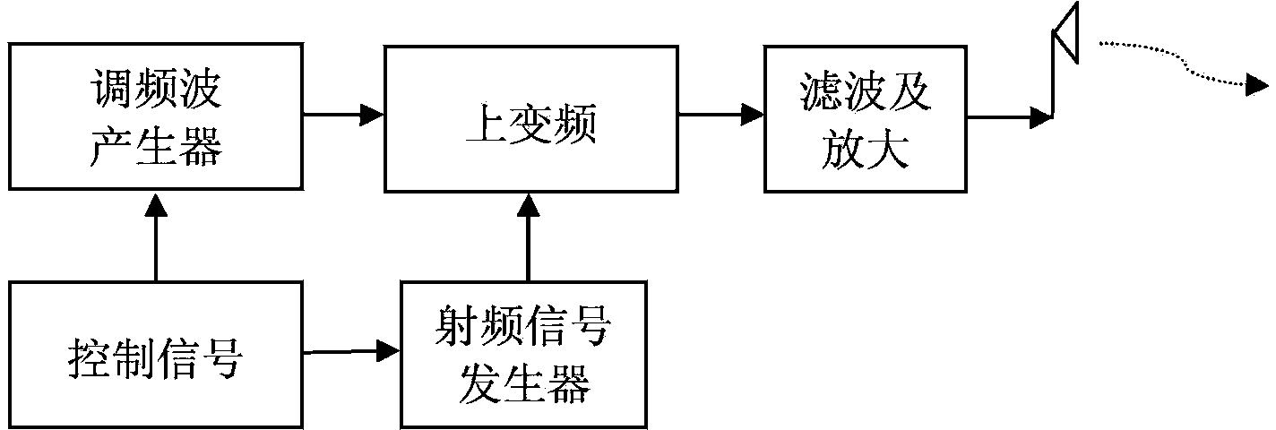
[0029] The transmitting unit 1 is respectively connected with the radio frequency signal generating unit 5 and the power device 7 that controls the rotation of the transceiver antenna; the receiving, amplifying, down-con...


PUM


Abstract

The invention provides a looking-around synthetic aperture imaging radar. The imaging radar comprises a launch unit 1, a receiving, amplifying, down-conversion and filtering unit 2, a signal processing and imaging unit 3, a display unit 4, a radio frequency signal generating unit 5, a control unit 6 and a power device 7 controlling rotating of a receiving antenna and a transmitting antenna. The looking-around synthetic aperture imaging radar is installed on a top platform of a ship, the transmitting antenna transmits electromagnetic waves to the periphery of the ship in the 360-degree direction, the receiving antenna receives electromagnetic wave signals reflected back by targets and sea waves and performs amplifying, down-conversion and sampling on the signals, and after arc synthetic aperture imaging signal processing, imaging processing and the like are preformed, an image display circuit displays the targets and the sea state information around the ship. The looking-around synthetic aperture imaging radar can replace an S / X wave band ship navigation radar widely applied currently and is used for guiding the ship to sail, ship collision is avoided, meanwhile, the looking-around synthetic aperture imaging radar has the function of inverting ocean kinetic parameters (waves and currents) around the ship, and therefore safety of navigation of the ship is ensured.

Description

technical field [0001] The invention belongs to the technical field of ship navigation, and in particular relates to a surround-view synthetic aperture imaging radar for monitoring targets and sea conditions around a ship to ensure safe navigation of the ship. Background technique [0002] Traditional ship navigation devices (such as ship-borne X / S-band navigation radar) use pulse system radar to monitor targets around the ship. This type of navigation device has the following disadvantages: 1. Due to the limitation of time-bandwidth product, if the distance resolution is high , the operating distance becomes smaller, and if the operating distance is large, the distance resolution becomes poor; 2. It belongs to the real aperture radar, and its azimuth resolution is limited by the antenna aperture, which is difficult to be further improved; 3. Magnetron emission technology is often used , is a non-coherent radar, which often requires higher transmission power and is prone to ...

Claims


Application Information

Patent Timeline
IPC IPC(8): G01S13/90G01S13/93
CPCG01S13/9082
Inventor 陈章友吴雄斌张兰王立
Owner WUHAN UNIV
Learn More