Wired electric appliance with cable clamp

A technology for wired electrical appliances and wire clips is applied in the field of structural design of limited electrical appliances, and can solve the problems of inconvenience in use, entanglement, and hindering the use of the next ligature.

Inactive Publication Date: 2013-10-23
国网山东省电力公司东营市垦利区供电公司 +2
View PDF6 Cites 1 Cited by
  • Summary
  • Abstract
  • Description
  • Claims
  • Application Information

AI Technical Summary

Problems solved by technology

[0002]Existing wired devices all have long cables, which are easily tangled into a mess when carried and stored, which is quite inconvenient to use
When these electrical appliances with cables leave the factory, their single cables are repeatedly folded to form a bundle of cables, and then tied on the bundle of cables with cable ties, cables or rubber bands. Disassemble the cable ties, cables or rubber bands, so the cable ties, cables and rubber bands are easily lost, which hinders the use of the next ligation
[0003] The existing wire clip includes a clamping piece and two clamping handles; the clamping piece includes two splints made in one piece, and the two sides of the end plate body of each splint are bent and rolled back toward the outside of the splint to form two pin holes; The clamping handle is made of steel wire, and each clamping handle includes two load-bearing parts. The two ends of the two load-bearing parts are bent to form two pins, and each pin is inserted in a corresponding pin hole; this structure It can make the cable clamp clamp on a single cable of a wired device by using its two splints, but it still cannot be used to tidy up the cable, so there is still room for improvement in its structure

Method used


Image

  • Wired electric appliance with cable clamp
  • Wired electric appliance with cable clamp
  • Wired electric appliance with cable clamp

Examples


Embodiment Construction

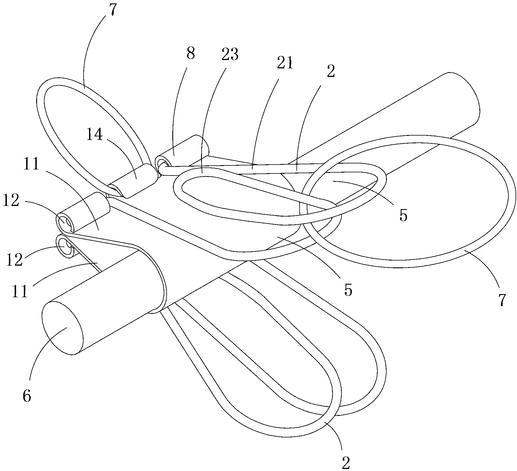
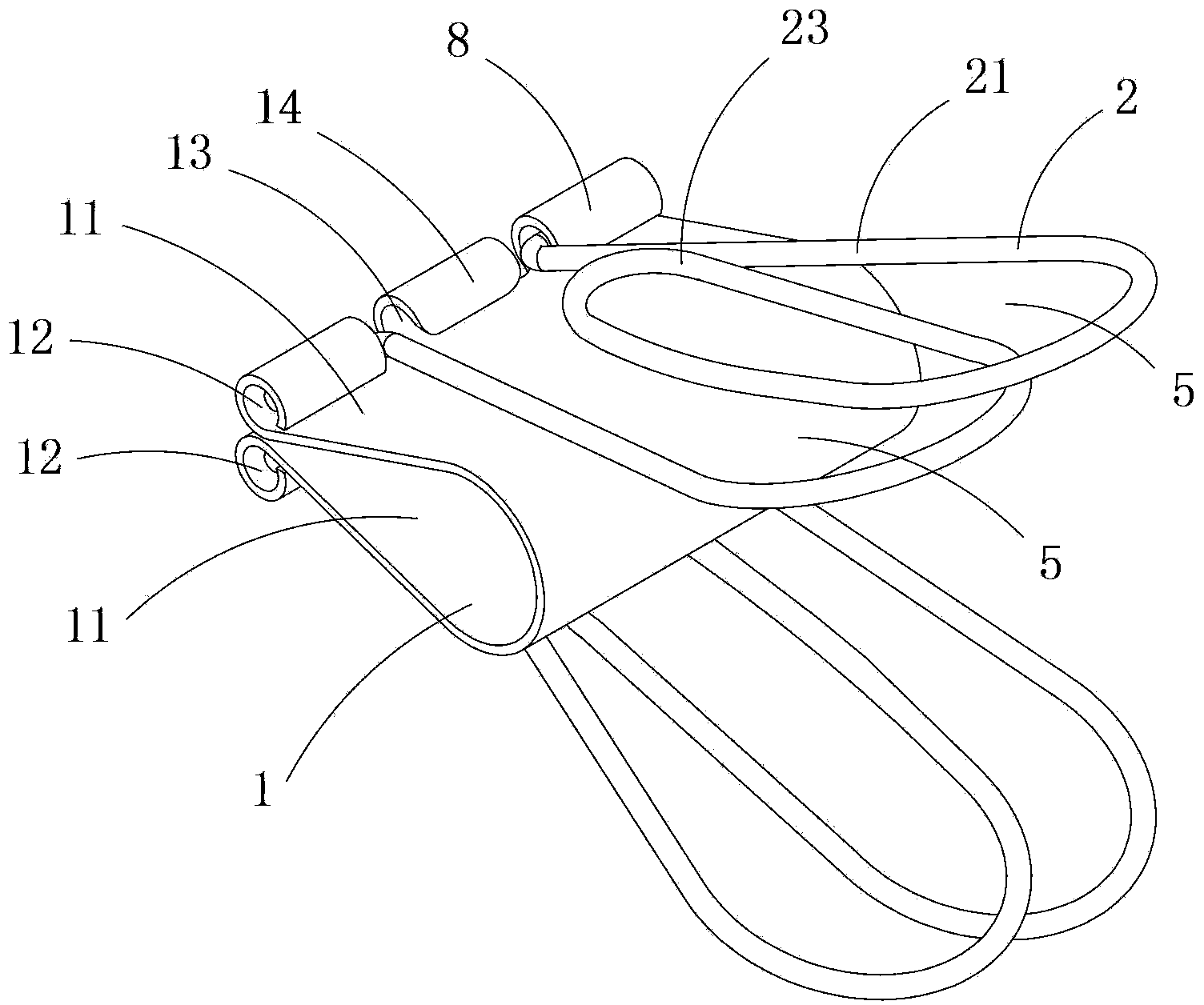
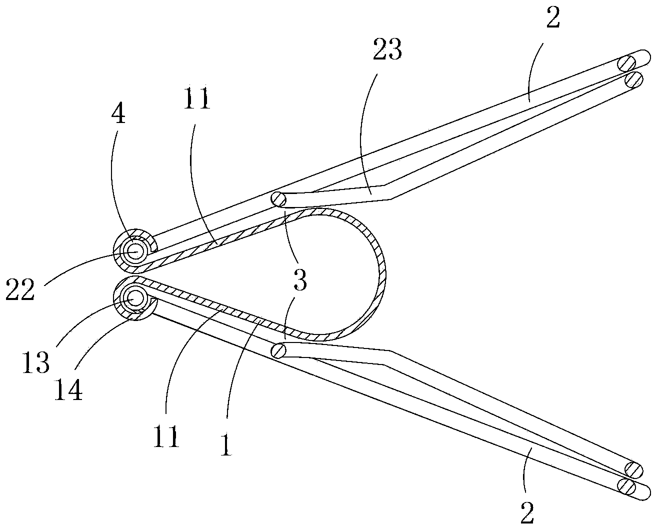
[0010] Figure 1 to Figure 3 A specific embodiment of the invention is shown in which, figure 1 It is a schematic diagram of a three-dimensional structure of the present invention; figure 2 yes figure 1 A schematic diagram of a three-dimensional structure of the long tail clip in the shown wired appliance; image 3 yes figure 2 A cutaway view of the long tail clip shown.

[0011] This embodiment is a wired electrical appliance with wire clips, see Figure 1 to Figure 3 , including a cable 6 connected to the finite electrical body and a wire clip 8 arranged on the cable, the wire clip includes a clamping piece 1 and two clamping handles 2; the clamping piece includes two splints 11 made in one piece, each The two sides of the plate at the end of the splint are bent and rolled back toward the outside of the splint to form two pin holes 12; each clamp handle is made of steel wire, and each clamp handle includes two load-bearing parts 21, and two load-bearing parts of the t...


PUM


Abstract

The invention discloses a wired electric appliance with a cable clamp. The wired electric appliance comprises a cable connected to a wired electric appliance body and the cable clamp arranged on the cable, wherein the cable clamp comprises a clamping connection element and two clamping handles; the clamping connection element comprises two integrally-formed clamp plates; two side ends of each clamp plate tail end board body are bent and rewound in the outer side direction of the each clamp plate to form two pin holes; each clamping handle is formed by a woven steel wire, and comprises two bearing parts; two tail ends of the two bearing parts are bent to form two pins; each pin is inserted into a corresponding pin hole; the middle end of each clamp plate tail end board body is bent and rewound in the outer side direction to form a clamping connecting part with a clamping hole; the cable clamp is connected to an elastic bounding ring through the clamping hole, is clamped on a single cable through the clamping connection element and is sleeved with a bundling cable formed by repeated superimposing of the single cable through the elastic bounding ring. The wired electric appliance has the advantages of convenience in use, and can neatly binds cables.

Description

technical field [0001] The invention belongs to the technical field of structural design of limited electric appliances, and in particular relates to a wired electric appliance with a wire clamp. Background technique [0002] Existing wired devices all have relatively long cables, which are easily tangled into a mess when being carried and stored, which is quite inconvenient to use. When these electrical appliances with cables leave the factory, their single cables are repeatedly folded to form a bundle of cables, and then tied on the bundle of cables with cable ties, cables or rubber bands. Disassemble the cable tie, cable or rubber band, so the cable tie, cable and rubber band are easily lost, which hinders the next ligation. [0003] The existing wire clip includes a clamping piece and two clamping handles; the clamping piece includes two splints made in one piece, and the two sides of the end plate body of each splint are bent and rolled back toward the outside of t...

Claims


Application Information

Patent Timeline
IPC IPC(8): B65D71/02
Inventor 胡妍
Owner 国网山东省电力公司东营市垦利区供电公司
Why Eureka
Try Eureka