Cast-in-place box beam lateral die sliding construction device and method

A construction device and side form technology, which is applied to bridges, bridge construction, erection/assembly of bridges, etc., can solve problems such as time-consuming and labor-intensive, complicated construction methods, and achieve economical, practical, and simple operation effects

Inactive Publication Date: 2013-10-16
中铁建大桥工程局集团电气化工程有限公司
View PDF8 Cites 15 Cited by
  • Summary
  • Abstract
  • Description
  • Claims
  • Application Information

AI Technical Summary

Problems solved by technology

It can be seen that the existing construction methods for cast-in-...

Method used


Image

  • Cast-in-place box beam lateral die sliding construction device and method
  • Cast-in-place box beam lateral die sliding construction device and method

Examples


Embodiment Construction

[0020] The present invention will be further described in detail below through specific embodiments in conjunction with the accompanying drawings. The following examples are only descriptive, not restrictive, and cannot limit the protection scope of the present invention.

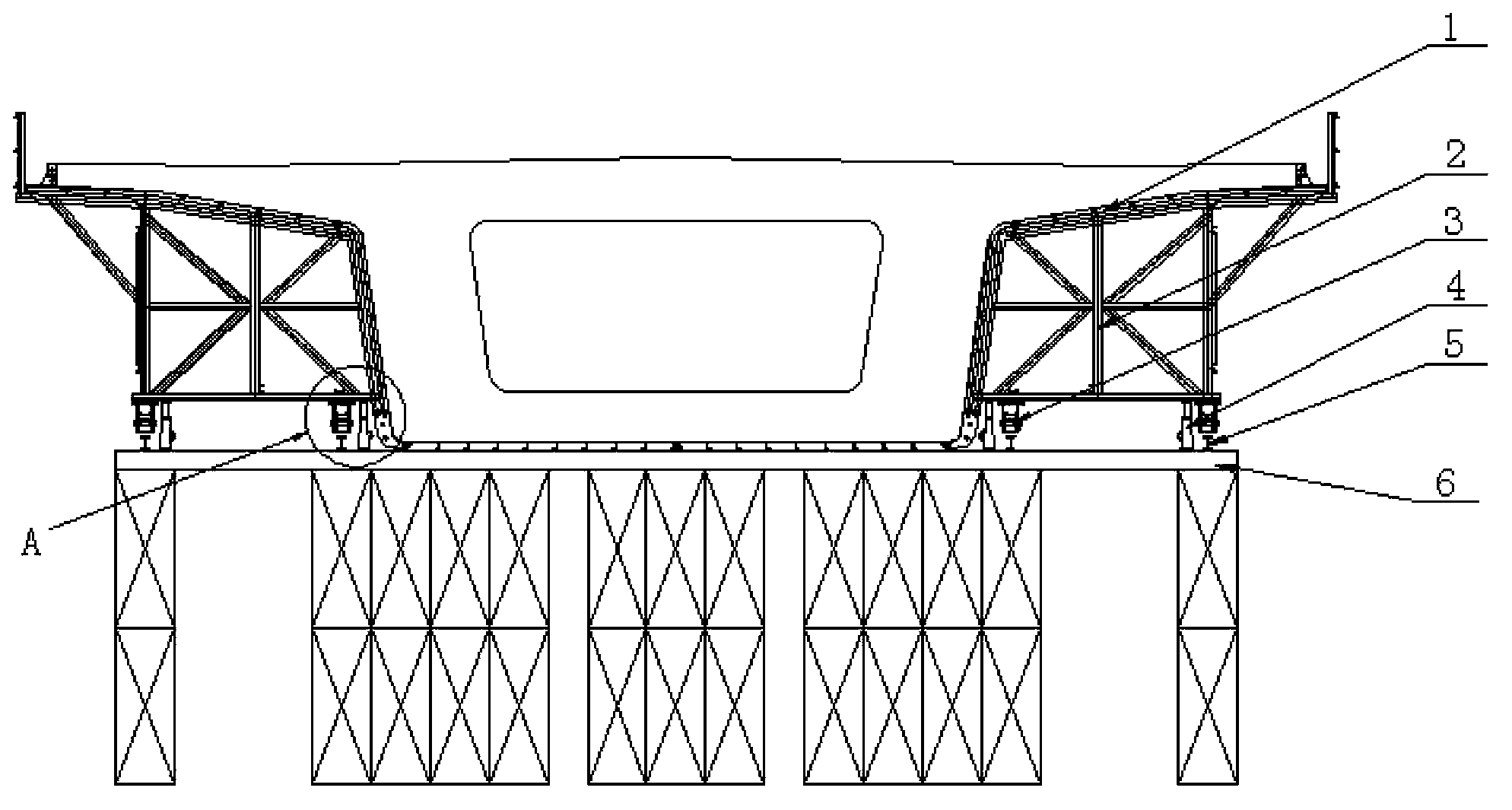
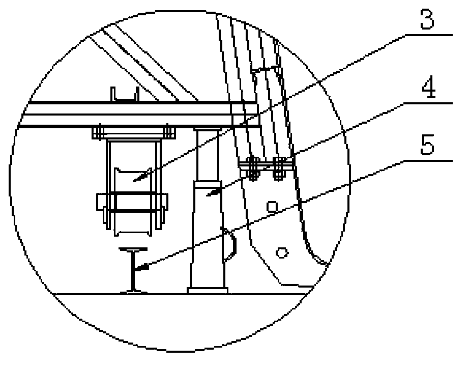
[0021] A cast-in-place box girder side form sliding construction device, which is composed of a movable side form, a sliding track 5 and a jack 4, and the movable side form is composed of a side form 1, a side form truss 2 and a fixed installation at the bottom of the side form truss Two rows of walking pulleys 3 are formed, and the side-by-side sliding rails are fixed on the support 6, and the movable side molds are movable and installed on the sliding rails, and jacks are symmetrically installed between the support top and the side mold bottoms. The jack position card is close to the position of the traveling pulley. The above-mentioned movable side forms and sliding tracks are the same structures locate...


PUM


Abstract

The invention relates to a cast-in-place box beam lateral die sliding construction device. The cast-in-place box beam lateral die sliding construction device is characterized by comprising a movable lateral die, a sliding rail and a lifting jack. The movable lateral die is composed of a lateral die body and a walking pulley which is fixedly arranged at the bottom of the lateral die body, the sliding rail is fixedly arranged on a support, the movable lateral die is movably installed on the sliding rail, and the lifting jack is installed between the upper portion of the support and the bottom of the lateral die. The invention further relates to a cast-in-place box beam lateral die sliding construction method. By the adoption of the cast-in-place box beam lateral die sliding construction device and method, the phenomenon that in the construction process of a traditional cast-in-place beam, a large number of hoisting devices and transport vehicles are needed for demounting, reshipping and hoisting the lateral die is effectively avoided, and the cast-in-place box beam lateral die sliding construction device and method are economical, practical, simple in operation, and capable of effectively saving expenditures, shortening labor hours, and possessing obvious economic benefits and social benefits.

Description

technical field [0001] The invention belongs to the technical field of bridge construction, in particular to a sliding construction device and method for a side form of a cast-in-place box girder. Background technique [0002] With the development of the national economy, the scale of urban overpasses, expressway viaducts, and high-speed railway viaducts has become larger and larger, and a large number of cast-in-place box girder constructions have occurred. The traditional construction method is: set up the support → install the side formwork → pave the bottom formwork → bind the bottom and web steel bars → install the inner formwork → bind the top plate steel bars and install the embedded parts → pour concrete → concrete curing → remove the formwork. In general, after pouring a box girder with one hole, the side forms need to be removed and transported back to the next hole box girder with a crane and a pallet truck, and then the side forms are installed with a crane. It ...

Claims


Application Information

Patent Timeline
IPC IPC(8): E01D21/00
Inventor 王勇崔淑斌黄建平
Owner 中铁建大桥工程局集团电气化工程有限公司
Why Eureka
Try Eureka