
Tool mechanism for clamping frame workpiece of robot workstation

A technology of workstations and robots, applied in auxiliary devices, manufacturing tools, metal processing equipment, etc., can solve problems such as troublesome positioning of parts, unstable quality, and large human factors, and achieve improved work efficiency, reduced idle time, and ingenious structure reasonable effect

Inactive Publication Date: 2013-10-16
上海气焊机厂有限公司
View PDF11 Cites 23 Cited by
  • Summary
  • Abstract
  • Description
  • Claims
  • Application Information

AI Technical Summary

Problems solved by technology

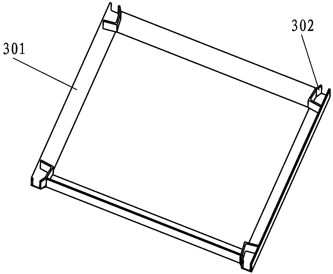
[0002] In the prior art, frame-type welding workpieces (i.e. frame-type workpieces, such as figure 1 The one shown is a typical frame-shaped workpiece) is a relatively special type of workpiece with a large variety and quantity. In the traditional process, spot welding is performed on the main joints of the frame-shaped workpiece in advance to form a After the complete frame structure is fixed, it is fixedly installed on the workbench of the robot workstation for welding. The whole process is complicated, and the positioning of each component in the spot welding process is also a troublesome problem.
[0003] When installed on the robot workstation workbench, manual adjustment and manual positioning are usually used. This positioning method has large human factors and the quality is not stable enough.

Method used


Image

  • Tool mechanism for clamping frame workpiece of robot workstation
  • Tool mechanism for clamping frame workpiece of robot workstation
  • Tool mechanism for clamping frame workpiece of robot workstation

Examples


Embodiment Construction

[0032] The present invention will be further described below in conjunction with the accompanying drawings and embodiments.

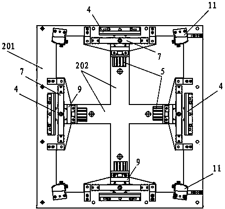
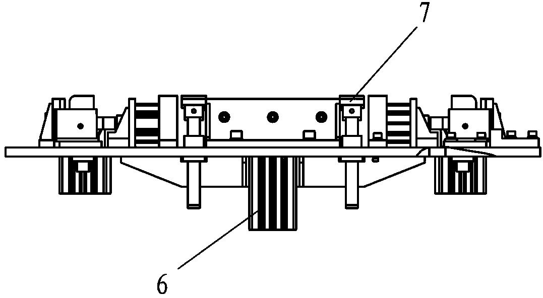
[0033] figure 2 , image 3 , Figure 4 , Figure 5 It shows a frame-shaped workpiece clamping tooling mechanism of a robot workstation, which includes a frame-shaped workpiece support that matches the frame-shaped workpiece, and the frame-shaped workpiece support 2 is connected to the main support 1 of the workbench of the robot workstation. Frame type workpiece support comprises four frame supports 201 and center support 202 that are fixedly connected, respectively is provided with frame type workpiece 3 (such as figure 1 The frame positioning blocks 4 matched with each frame shown in ) are provided with a clamping cylinder 5 on the inside of each frame positioning block 4, and the clamping cylinder 5 is fixedly connected with the center bracket 202, so The ejector rod of the jacking cylinder 5 can stably fix and position the four frames 301 of th...


PUM


Abstract

The invention discloses a tool mechanism for clamping a frame workpiece of a robot workstation. The mechanism comprises frame workpiece supports matched with the frame workpiece, wherein frame positioning blocks matched with workpiece frames are arranged on four frame supports; ejection air cylinders are arranged on inner sides of the frame positioning blocks; ejection rods of the ejection air cylinder are ejected, so that four frames of the frame workpiece are fixed and positioned stably in positions corresponding to the frame positioning blocks; and workpiece ejection mechanisms are arranged corresponding to the frames of the frame workpiece on the frame supports. The tool mechanism for clamping the frame workpiece of the robot workstation is ingenious and reasonable in structure; and the four scattered frames of the frame workpiece are directly positioned and fixed on the frame workpiece supports through arrangement of the ejection air cylinders and the frame positioning blocks, so that a complex underneath electric welding process in which positioning errors are prone to occur is not required, the workpice supports can be directly fixed and welded, the work efficiency is greatly improved, and the work errors are also greatly reduced.

Description

technical field [0001] The invention relates to a tooling mechanism, in particular to a tooling mechanism for a robot workstation. Background technique [0002] In the prior art, frame-type welding workpieces (i.e. frame-type workpieces, such as figure 1 The one shown is a frame-shaped typical workpiece) is a relatively special type of workpiece with a large variety and quantity. In the traditional process, spot welding is performed on the main joints of the frame-shaped workpiece in advance to form a After completing the frame structure, it is fixedly installed on the workbench of the robot workstation for welding. The whole process is complicated, and the positioning of each component in the spot welding process is also a troublesome problem. [0003] And when it is installed on the workbench of the robot workstation, manual adjustment and manual positioning are usually used. This positioning method has a large human factor and the quality is not stable enough. Contents...

Claims


Application Information

Patent Timeline
Patent Type & Authority Applications(China)
IPC IPC(8): B23K37/04
Inventor 陈友虞丁书才
Owner 上海气焊机厂有限公司
Learn More