
Double-film refraction and reflection type co-detector imaging system

An imaging system and catadioptric technology, applied in the field of optics, can solve the problems of the steep increase in the design difficulty of the total reflection optical system, the poor imaging performance of the off-axis system, and the inability to use the two-reflection system, etc., to achieve compact structure, easy chromatic aberration correction, The effect of small distortion

Active Publication Date: 2013-10-09
CHANNGCHUN CHANGGUANG ADVANCED OPTICS TECH CO LTD
View PDF5 Cites 19 Cited by
  • Summary
  • Abstract
  • Description
  • Claims
  • Application Information

AI Technical Summary

Problems solved by technology

Dual-band infrared detectors are generally cooled detectors, so there is a cold stop in the detector. The existence of the cold stop makes the total reflection optical system have to perform secondary imaging to achieve cold stop matching, which makes it impossible to use the most widely used Two-mirror system design (two-reverse Gregorian system can realize secondary imaging, but the imaging performance of off-axis system is poor, so it cannot be applied)
However, when a compact form factor and a large field of view are required, the design challenge of total reflection optical systems increases dramatically

Method used


Image

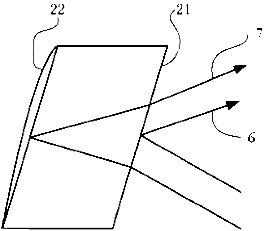
  • Double-film refraction and reflection type co-detector imaging system
  • Double-film refraction and reflection type co-detector imaging system
  • Double-film refraction and reflection type co-detector imaging system

Examples


Embodiment Construction

[0018] The present invention will be described in further detail below in conjunction with the accompanying drawings and embodiments.

[0019] figure 1 and figure 2 A schematic diagram of the optical path of the dual-mode catadioptric common-detector imaging system is given, figure 1 The optical path of the imaging system for 3.7μm-4.8μm mid-wave infrared is given, figure 2 The optical path of the imaging system for 8 μm ~ 10 μm long-wave infrared is given in . From the object side to the image side, it consists of a primary mirror 1, a secondary mirror 2, a relay mirror group 4 and a focal plane detector 5 in sequence.

[0020] The imaging system uses a two-mirror Cassegrain system with two high-order aspheric surfaces. The secondary mirror 2 is a convex gold mirror, and its material is germanium. All optical elements are arranged on the same optical axis, the primary mirror 1 has a central hole, the secondary mirror 2 is placed in front of the primary mirror 1, the re...


PUM

PropertyMeasurementUnit
Thickness rangeaaaaaaaaaa

Abstract

The invention provides a double-film refraction and reflection type co-detector imaging system, and belongs to the technical field of optics. The system comprises a primary mirror, a secondary mirror, a relay mirror group and a focal plane detector, wherein the primary mirror, the secondary mirror, the relay mirror group and the focal plane detector are placed sharing the same optical axis; the primary mirror and the secondary mirror are of a Cassegrain structure; the primary mirror is provided with a central hole, the secondary mirror is placed in front of the primary mirror, and the relay mirror group and the focal plane detector are placed at the back of the secondary mirror; the secondary mirror is a Mangin mirror, the front surface of the secondary mirror reflects medium wave infrareds and transmits long wave infrareds, and the back surface of the secondary mirror reflects long wave infrareds; arrangement of the two reflecting surfaces of the secondary mirror enables the medium wave infrareds and the long wave infrareds to be the same in optical distance so as to enable the medium wave infrareds and the long wave infrareds to be imaged on the same focal plane under the condition without focusing. The system can achieve two-waveband operation and imaging in a long focal distance and with a large relative aperture, and is compact in structure and little in distortion, a transfer function reaches or is close to a diffraction limit, and cold aperture matching reaches 100%.

Description

technical field [0001] The invention belongs to the field of optical technology, and relates to an infrared mid-wave / long-wave dual-mode catadioptric common-detector imaging system. Background technique [0002] With the development of a new generation of multi-band infrared detector technology, the use of multi-band imaging has become more and more widespread. In order to successfully apply the new generation of detectors, it is necessary to design an optical system capable of multi-band imaging at the same time. [0003] In the field of infrared imaging, the most widely used spectral bands are mid-wave infrared (3μm-5μm) and long-wave infrared (8μm-12μm). These two bands have different advantages and limitations compared to each other. The best way is to use a dual-band infrared detector to combine the above two bands so that their advantages complement each other. [0004] The main problem in the design of dual-band optical systems is that the dispersion characteristics...

Claims


Application Information

Patent Timeline
IPC IPC(8): G02B17/08
Inventor 付强张新史广维王灵杰张建萍
Owner CHANNGCHUN CHANGGUANG ADVANCED OPTICS TECH CO LTD
Learn More