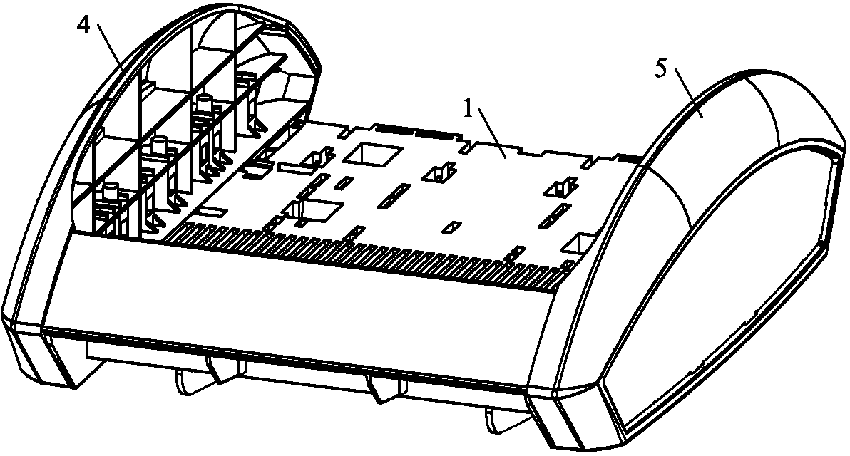
Goods shelf capable of being regulated in multiple directions
A multi-directional adjustment and shelf technology, which is applied in display shelves, display hangers, display stands, etc., can solve the problems of high cost, small adjustable range, and no step-like layering in the appearance of multi-layer laminates, so as to achieve versatility Strong, cost-saving, and strong marketing effects
- Summary
- Abstract
- Description
- Claims
- Application Information
AI Technical Summary
Problems solved by technology
Method used
Image
Examples
Embodiment 1
[0031] Such as Figure 1 to Figure 6 As shown, the direction of this embodiment is figure 2 The placement direction of the shown multi-directional adjustable shelf shall prevail. A multi-directional adjustable shelf in this embodiment includes a laminate 1 and a bracket 2, the laminate 1 is connected to the bracket 2, and also includes The telescopic rod 3 transversely runs through the laminate 1 , and the side end of the laminate 1 is provided with a side cover, and the side cover is telescopically connected with the laminate 1 through the telescopic rod 3 . When the present invention is in use, the increase of the length of the laminate 1 can be realized by stretching the side cover. An extension area is formed between the side ends of the board 1, and the goods can be directly placed in the extension area, and ordinary pallets can also be placed on the telescopic rod 3 in the extension area and then the goods are placed. When returning to the original size, it is only ne...
Embodiment 2
[0041] Such as Figure 7 , Figure 8 As shown, the difference between this embodiment and Embodiment 1 is that the number of laminates 1 described in this embodiment is at least two, and a connecting piece 9 is provided between every two adjacent laminates 1, which is consistent with the The laminate 1 connected to the left cover 4 and the laminate 1 connected to the right cover 5 are respectively the first laminate and the second laminate, which are arranged on the first laminate and the second laminate. The laminate 1 between is the middle laminate; the first telescopic rod 31 of the first laminate is connected to the left side cover 4, and the second telescopic rod 32 of the first laminate is connected to the first telescopic rod 32 of the first laminate. The connecting piece 9 adjacent to the laminate; the second telescopic rod 32 of the second laminate is connected to the right side cover 5, and the first telescopic rod 31 of the second laminate is connected to the secon...
Embodiment 3
[0044] Such as Figure 9 , Figure 10 As shown, the difference between the present embodiment and the second embodiment is that: the connecting end of the present embodiment is provided with a perforation 724, and the bracket 2 is also provided with a crossbeam 22, and the crossbeam 22 is set through the perforation 724, the two ends of the beam 22 are provided with two positioning pieces 23, and several positioning pin holes 24 are opened on the two positioning pieces 23, and several positioning pin holes 24 are arranged in an arc shape, and the Both ends of the beam 22 are respectively fixed to the bracket 2 by two positioning pieces 23 . Crossbeam 22 is connected with support 2 by locating piece 23, because the locating pin hole 24 on the locating piece 23 is arranged in arc shape, therefore crossbeam 22 and support 2 are connected and positioned by locating pin by different locating pin hole 24, can make The crossbeam 22 has different connection angles with respect to th...
PUM
 Abstract
Description
Claims
Application Information
 - R&D
- Intellectual Property
- Life Sciences
- Materials
- Tech Scout
- Unparalleled Data Quality
- Higher Quality Content
- 60% Fewer Hallucinations
Browse by: Latest US Patents, China's latest patents, Technical Efficacy Thesaurus, Application Domain, Technology Topic, Popular Technical Reports.
© 2025 PatSnap. All rights reserved.Legal|Privacy policy|Modern Slavery Act Transparency Statement|Sitemap|About US| Contact US: help@patsnap.com


