
Light guide plate pattern machining equipment

A technology for processing equipment and light guide plates, applied in metal processing equipment, laser welding equipment, welding equipment, etc., can solve the problems of decreased processing accuracy, poor continuity of processing process, and low processing efficiency.

Active Publication Date: 2013-10-02
SUZHOU DONGSHAN PRECISION MANUFACTURING CO LTD
View PDF8 Cites 7 Cited by
  • Summary
  • Abstract
  • Description
  • Claims
  • Application Information

AI Technical Summary

Problems solved by technology

[0004] However, although the above-mentioned processing process can meet the basic processing needs of the light guide plate pattern, since its Y-axis variable speed motion and X-axis reciprocating motion require frequent acceleration and deceleration, the inertia generated during the frequent speed change process will increase the processing equipment. The machine body vibrates, which leads to an increase in the processing error of the light guide plate pattern and a decrease in processing accuracy; at the same time, the laser processing operation cannot be performed during the acceleration and deceleration time of the relevant components, the continuity of the processing process is poor, and the processing efficiency is low.

Method used


Image

  • Light guide plate pattern machining equipment

Examples


Embodiment Construction

[0021] The core of the present invention is to provide a light guide plate pattern processing device, which has high processing precision and high processing efficiency.

[0022] In order to enable those skilled in the art to better understand the solution of the present invention, the present invention will be further described in detail below in conjunction with the accompanying drawings and specific embodiments.

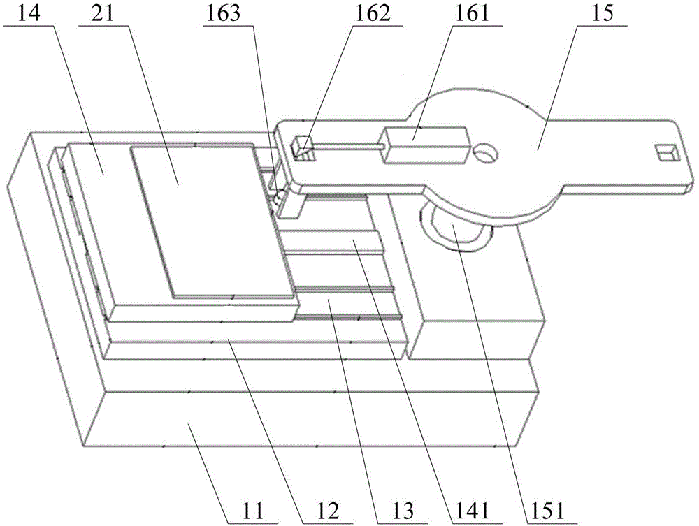
[0023] Please refer to figure 1 , figure 1 It is a schematic diagram of the assembly structure of the light guide plate pattern processing equipment provided by a specific embodiment of the present invention.

[0024] In a specific embodiment, the light guide plate pattern processing equipment provided by the present invention includes a frame 11, a support plate 12 is provided on the top of the frame 11, a guide rail 13 is provided on the support plate 12, and a guide rail 13 is movably provided with a The mobile platform 14 matched with the light guide plate 2...


PUM


Abstract

The invention discloses light guide plate pattern machining equipment. The top of a rack of the equipment is provided with a supporting plate; a guide rail is arranged on the supporting plate and is movably provided with a movable platform which is matched with a light guide plate; the rack is provided with a first driving device which can drive the movable platform to move along the extension direction of the guide rail; one end of the guide rail is provided with a rotary plate; the rotary plate is provided with a laser emitter; the edge of the upper surface of the rotary plate is provided with an optical reflector which is matched with the laser emitter; the optical reflector is positioned on an optical path of the laser emitter; a light collecting lens which is matched with the optical reflector and the light guide plate respectively is arranged below the optical reflector and is positioned on a reflecting optical path of the optical reflector; the rack is provided with a second driving device capable of driving the rotary plate to perform fixed-axis rotation; and the rotary plane of the rotary plate is parallel to the upper surface of the movable platform. The light guide plate pattern machining equipment has higher machining accuracy and machining efficiency.

Description

technical field [0001] The invention relates to the technical field of precision processing equipment for light guide plates, in particular to a pattern processing equipment for light guide plates. Background technique [0002] In the current field of optical equipment processing, in order to change the side-illuminated light source from a line light source to a uniform surface light source, it is necessary to carry out precise pattern processing on the light guide plate that is compatible with the light source. With the continuous improvement of use requirements, People have also put forward higher requirements on the performance of the light guide plate pattern processing equipment. [0003] At present, the existing light guide plate pattern processing equipment usually includes a mobile platform respectively arranged on the Y-axis guide rail and a laser lens arranged on the X-axis guide rail. The laser beam is collected and refracted to the processing surface of the ligh...

Claims


Application Information

Patent Timeline
IPC IPC(8): B23K26/36B23K26/08
Inventor 赵昌源袁永刚
Owner SUZHOU DONGSHAN PRECISION MANUFACTURING CO LTD
Learn More