
Apparatus for purifying exhaust air

A technology that discharges air and cleans it. It is applied to combined devices, using liquid separating agents, and separating particles. It can solve the problems of increased pressure loss of discharge air flow, high energy consumption, and loss of device efficiency, and achieves a reduction in liquid loss. Effect

Inactive Publication Date: 2013-09-25
BIG DUTCHMAN INT +1
View PDF4 Cites 0 Cited by
  • Summary
  • Abstract
  • Description
  • Claims
  • Application Information

AI Technical Summary

Problems solved by technology

In order to avoid this, it is theoretically possible to lengthen the particle separator, but in addition to a greater installation space requirement and increased construction costs, the pressure loss of the exhaust air flow flowing through the flow channel will also increase, which will lead to Significant loss of efficiency of the unit and higher energy consumption

Method used


Image

  • Apparatus for purifying exhaust air

Examples


Embodiment Construction

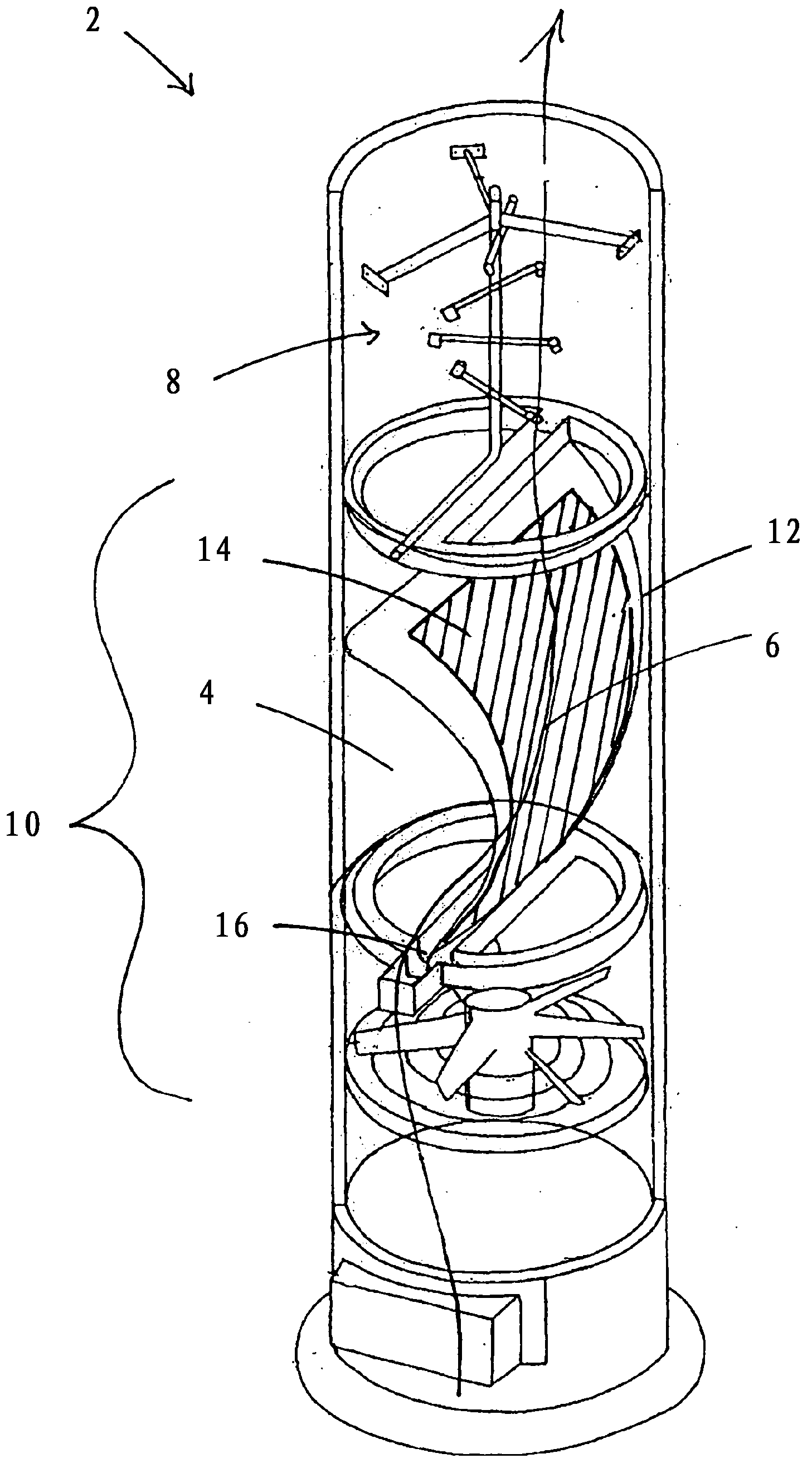
[0021] The device 2 has a flow channel 4 through which an exhaust air flow 6 flows in the flow direction. Located in the flow channel 4 is a liquid injection device 8 , by means of which liquid can be injected into the discharge air flow 6 . In the present exemplary embodiment, the flow channel 4 has a substantially vertical course, wherein the exhaust air flow 6 flows through the flow channel 4 from bottom to top. At a wind speed of the discharge air stream 6 in the device 2, which usually varies in the range of 5 m / s to 9 m / s, the droplets of the liquid sprayed by the liquid ejection device 8 are not forced to follow the flow direction of the discharge air stream 4 Instead, the droplets fall downwards against the direction of flow of the discharge air stream 4 under the force of gravity. The droplets thus reach the region of the particle separator 10 .

[0022] Unlike the present exemplary embodiment, the particle separator 10 can also be arranged downstream of the liquid ...


PUM

PropertyMeasurementUnit
thicknessaaaaaaaaaa

Abstract

The present invention relates to an apparatus (2) for purifying exhaust air with a flow channel (4), through which an exhaust air flow (6) to be purified can be passed, with a liquid spraying apparatus (8) which is arranged in the flow channel (4) and with which a liquid can be sprayed into the exhaust air flow (6), with a particle separator (10) with a collecting surface (12) arranged at an angle for collecting the liquid falling as drops and / or as aerosol from the exhaust air flow (6) and with a liquid discharge apparatus (8) associated with the collecting surface (12). In order to improve the previously known apparatus for purifying the exhaust air to the extent that less water tends to exit from the apparatus at the bottom, it is proposed that the surface of the collecting surface (12) is provided entirely or partially with a material (14) with a porous structure.

Description

technical field [0001] The invention relates to a device for cleaning exhaust air, which has a flow channel, a liquid injection device arranged in the flow channel, a particle separator and a liquid discharge device, through which the exhaust air flow to be cleaned can flow. a flow channel through which a liquid can be sprayed into the discharge air flow by means of the liquid injection device, the particle separator has an oblique arrangement for collecting particles falling out of the discharge air flow in the form of liquid droplets and / or aerosols A collecting surface for the liquid, to which the liquid discharge device is assigned. Background technique [0002] It is known from the prior art to separate gases, liquids or solids from an exhaust air flow by spraying the exhaust air flow with one or more liquids in a flow channel. The one or more liquids can be water or chemicals that combine (possibly chemically react) with the gases, liquids and solids carried in the ex...

Claims


Application Information

Patent Timeline
Patent Type & Authority Applications(China)
IPC IPC(8): B01D45/10B01D50/00B01D47/06B01D47/02
CPCB01D45/10B01D47/028B01D47/06B01D47/02B01D50/00
Inventor 托马斯·波尔迈尔
Owner BIG DUTCHMAN INT
Learn More