
Monitoring and pre-warning method and system for coal mine roadway roof collapse disaster

A technology for monitoring and early warning, coal mine roadway, applied in mining equipment, mining equipment, earthwork drilling, etc.

Active Publication Date: 2013-09-25
YOULUOKE AUTOMATION INSTR TAIAN
View PDF6 Cites 12 Cited by
  • Summary
  • Abstract
  • Description
  • Claims
  • Application Information

AI Technical Summary

Problems solved by technology

[0003] In the prior art, disaster identification and early warning are usually carried out based on the amount of abscission, or the velocity of abscission, or the acceleration of abscission. The judgment method is one-sided, and the early warning threshold is difficult to determine due to the complexity of the rock formations that make up the roof. It brings difficulties to the identification and early warning of roof fall disasters

Method used


Image

  • Monitoring and pre-warning method and system for coal mine roadway roof collapse disaster
  • Monitoring and pre-warning method and system for coal mine roadway roof collapse disaster
  • Monitoring and pre-warning method and system for coal mine roadway roof collapse disaster

Examples


Embodiment 1

[0113] Step 1: Install a monitoring and early warning system.

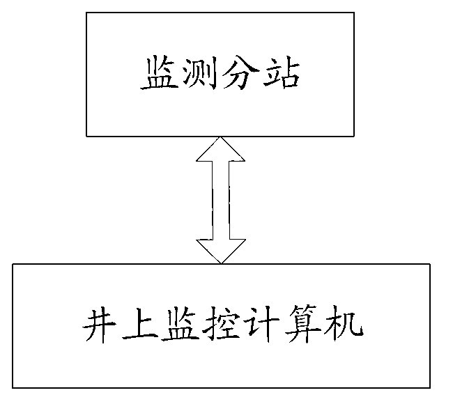
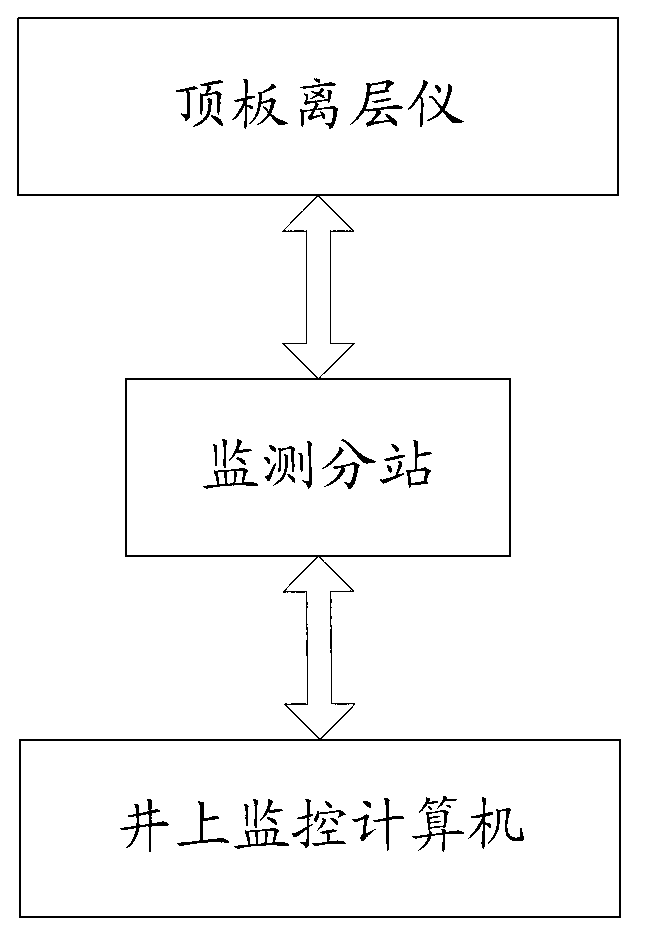
[0114] according to image 3 As shown, drill a row of holes into the roof every 15-25 meters along the direction of the roadway (each hole corresponds to a monitoring point), press Figure 4 As shown, install the roof separation instrument in the borehole, and ensure that the two monitoring points of the roof separation instrument are distributed on the deep base point and the shallow base point of the rock formation. The substations are connected through the CAN bus, and the monitoring substations are connected with the monitoring computer on the well through the downhole network system to form a monitoring and early warning system.

[0115] One monitoring substation can be connected to multiple roof separation instruments. At present, 128 roof separation instruments can be connected within a range of 5km by using the CAN bus. After the CAN bus is expanded by using a repeater, theoretically, countless roof separ...

Embodiment 2

[0135] according to image 3 Drill holes in the center of the roof of the roadway every 20 meters along the direction of the roadway as shown, the diameter of the hole is Φ27-29mm, according to Figure 4 Install the roof delamination instrument as shown, push the two anchor claws to the required depth with the installation rod, ensure that the two monitoring points of the roof delamination instrument are fixed on the deep base point and the shallow base point, and anchor them. Connect the monitoring substation with the roof separation instrument through the CAN bus, and then connect the monitoring substation with the monitoring computer on the well through the downhole network system to form a monitoring and early warning system.

[0136] Assume that the data sequence collected by a certain plate delamination instrument is shown in the following table (where t m The abscission amount corresponding to each moment is the latest measured data):

[0137] time

... ...


PUM


Abstract

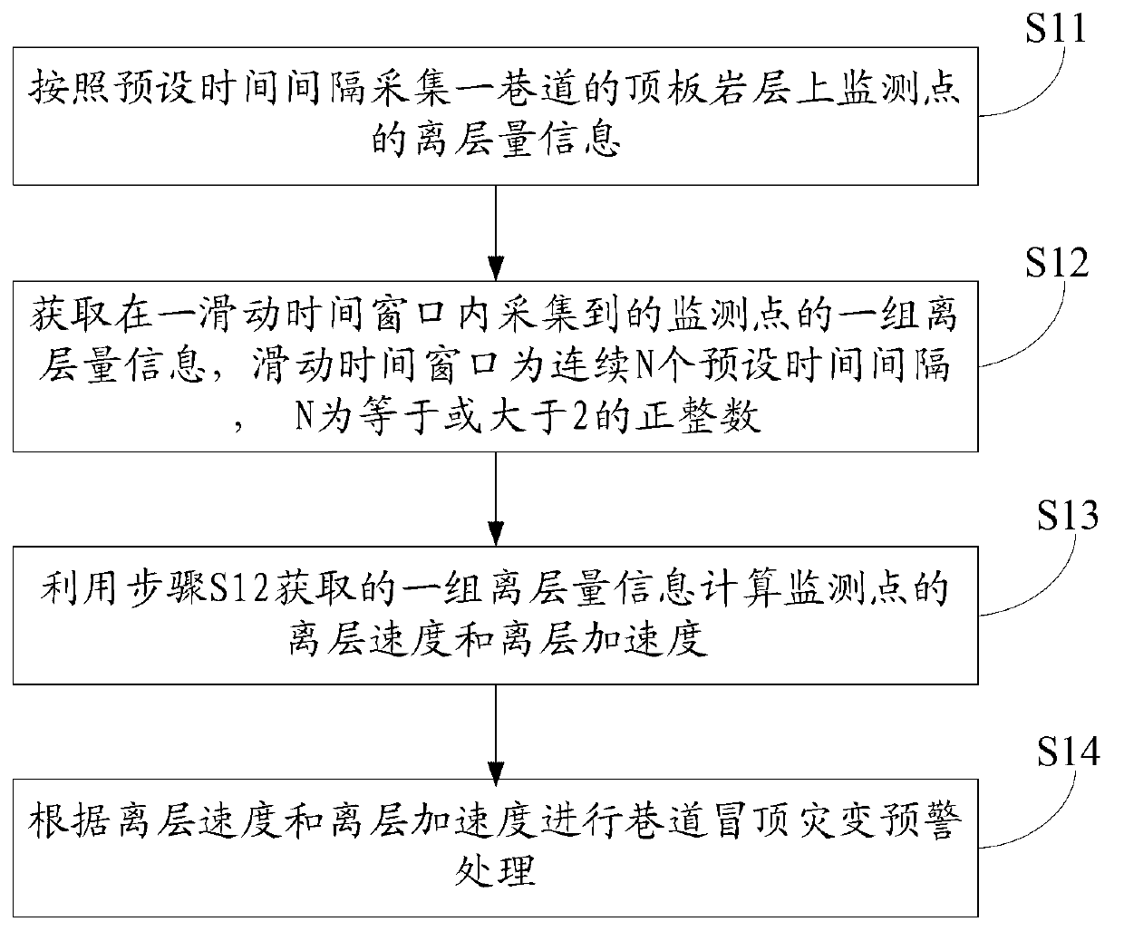
An embodiment of the invention provides a monitoring and pre-warning method and system for a coal mine roadway roof collapse disaster, and aims to provide an accurate and timely monitoring and pre-warning technique for the roof collapse disaster. According to the monitoring and pre-warning method and system for the coal mine roadway roof collapse disaster, through acquired continuous real-time data of a roof separation layer, a separation layer speed and an accelerated speed are calculated and integrated to perform monitoring and pre-warning of the coal mine roadway roof collapse disaster; the monitoring and pre-warning technique integrates the separation layer speed and the accelerated speed, so that the roof separation layer tendency can be more intuitively reflected; and the technique has the advantages of large data acquisition density, accurate separation layer tendency analysis, timely pre-warning and the like, moreover, algorithm processing is simple and direct, the complexity is smaller, and the requirement for the timeliness of the roadway roof collapse pre-warning can be met.

Description

technical field [0001] The invention relates to the field of safety science and engineering technology, in particular to a method and system for monitoring and early warning of roof fall disasters in coal mine roadways. Background technique [0002] Roadway roof fall disaster is one of the major threats to coal mine safety production. Many scholars at home and abroad have carried out a lot of research work on the monitoring and early warning technology of roadway roof fall disaster. Because the coal mine roof is generally a typical layered structure, the amount of roof separation is used as one of the important index data for judging roadway roof fall catastrophe. [0003] In the prior art, disaster identification and early warning are usually performed based on the amount of abscission, or the velocity of abscission, or the acceleration of abscission. The judgment method is one-sided, and the early warning threshold is difficult to determine due to the complexity of the roc...

Claims


Application Information

Patent Timeline
Patent Type & Authority Applications(China)
IPC IPC(8): E21F17/18
Inventor 闫相宏贾瑞生李建中李莉高丽丽孙君李娟沈文众江霞郭斌张勇吴亮
Owner YOULUOKE AUTOMATION INSTR TAIAN
Learn More