Rotary working table of vertical wood splitting machine

A technology of rotating workbench and workbench, which is applied in the direction of wood splitting devices, wood processing equipment, manufacturing tools, etc., which can solve the problems of inconvenient use for users, and achieve the effect of increasing the speed of wood splitting and being easy to use

Inactive Publication Date: 2013-09-25
YANGZHOU XINGYI MACHINERY
View PDF0 Cites 2 Cited by
  • Summary
  • Abstract
  • Description
  • Claims
  • Application Information

AI Technical Summary

Problems solved by technology

[0002] The workbench of the original vertical wood splitter is divided into three gears. When splitting wood with different lengths, the workbench must be shifted according to the length of the wood, which is not very convenient for users to use.

Method used


Image

  • Rotary working table of vertical wood splitting machine

Examples


Embodiment Construction

[0008] Specific embodiments of the present invention will be described in detail below in conjunction with the accompanying drawings.

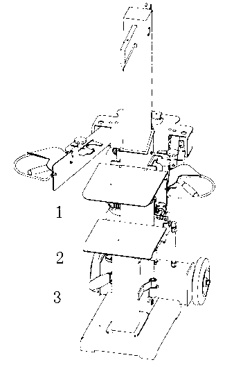
[0009] Such as figure 1 Shown: a vertical log splitter rotary table, including frame, upper table 1, rotary table 2 and fixed table 3, the fixed table 3 is installed at the bottom of the frame, the upper part of the frame A detachable upper table 1 is installed, and a movable rotary table 2 is installed between the upper table 1 and the fixed table 3 .

[0010] It should be pointed out that those skilled in the art can make some improvements and modifications without departing from the principle of the present invention, and these improvements and modifications should also be regarded as the protection scope of the present invention. All components that are not specified in this embodiment can be realized by existing technologies.


PUM


Abstract

The invention discloses a rotary working table of a vertical wood splitting machine. The rotary working table of the vertical wood splitting machine comprises a rack, an upper working table, the rotary working table and a fixed working table, wherein the fixed working table is arranged at the bottom of the rack, the detachable upper working table is arranged at the upper part of the rack, and the moveable rotary working table is arranged between the upper working table and the fixed working table. The three gear positions of the working tables of the wood splitting machine can be switched quickly, so that the wood splitting speed is increased and convenience is brought to users.

Description

technical field [0001] The invention relates to an electric tool, in particular to a rotary workbench of a vertical wood splitter. Background technique [0002] The workbench of the original vertical wood splitter is divided into three gears. When splitting wood with different lengths, the workbench must be shifted according to the length of the wood, which is not very convenient for users to use. Contents of the invention [0003] The purpose of the present invention is to overcome the deficiencies of the prior art, and to provide a rotary workbench of a vertical wood splitter. [0004] The technical solution adopted in the present invention is: a rotary workbench of a vertical wood splitter, comprising a frame, an upper workbench, a revolving workbench and a fixed workbench, the fixed workbench is installed on the bottom of the frame, and the A detachable upper worktable is installed on the upper part, and a movable rotary worktable is installed between the upper workta...

Claims


Application Information

Patent Timeline
Patent Type & Authority Applications(China)
IPC IPC(8): B27L7/00
Inventor 杨卫平孙增中左伟伟
Owner YANGZHOU XINGYI MACHINERY
Why Eureka
Try Eureka