Ejection rod structure for press plate of paper shredder

A paper shredder and press plate technology, which is applied in the direction of grain processing, etc., can solve the problems of affecting the paper shredding efficiency of the paper shredder, affecting the effect of paper grasping, and unevenness of the paper.

Inactive Publication Date: 2014-12-17
NINGBO HAIBO OFFICE MACHINERY
View PDF6 Cites 0 Cited by
  • Summary
  • Abstract
  • Description
  • Claims
  • Application Information

AI Technical Summary

Problems solved by technology

In the process of use, it is necessary to use the pressure plate to give a certain pressure to the paper to facilitate the cutter to pick the paper, but the paper that needs to be shredded often has staples or paper clips, which will cause unevenness of the stacked paper, and the pressure plate is a standard In the process of applying pressure to the paper, it will cause uneven force on the paper, which will affect the effect of paper grabbing, and then affect the shredding efficiency of the shredder

Method used


Image

  • Ejection rod structure for press plate of paper shredder
  • Ejection rod structure for press plate of paper shredder
  • Ejection rod structure for press plate of paper shredder

Examples


Embodiment Construction

[0018] Below in conjunction with specific embodiment, further illustrate the present invention. It should be understood that these examples are only used to illustrate the present invention and are not intended to limit the scope of the present invention. In addition, it should be understood that after reading the teachings of the present invention, those skilled in the art can make various changes or modifications to the present invention, and these equivalent forms also fall within the scope defined by the appended claims of the present application.

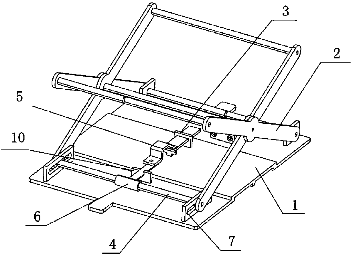
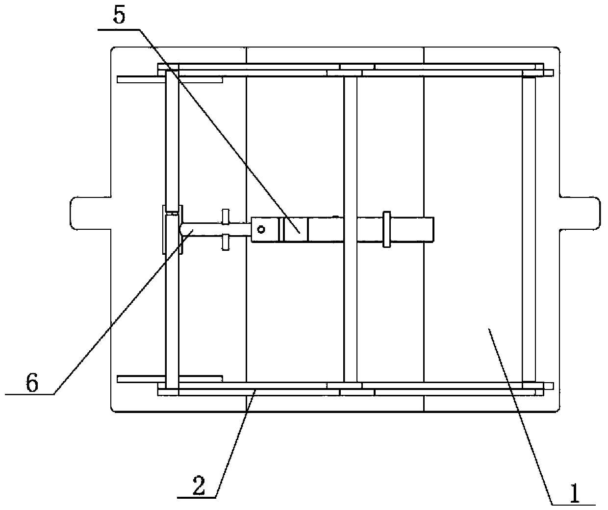
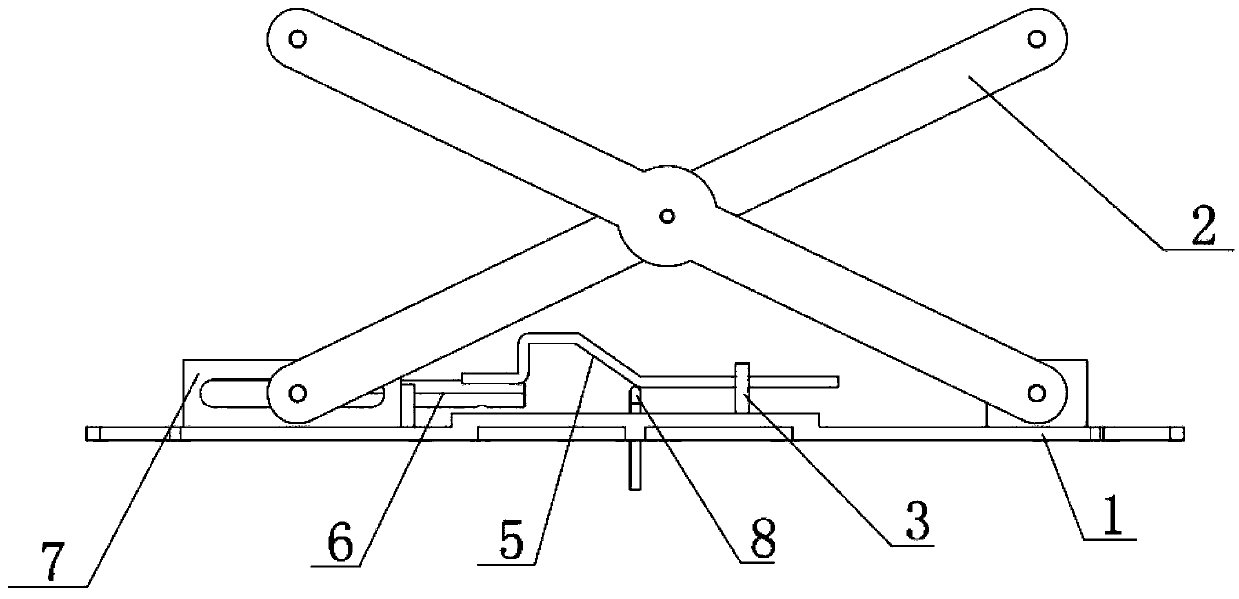
[0019] Such as Figure 1-6 As shown, the embodiment of the present invention relates to a push rod structure of a paper shredder press plate, including a press plate 1, an X-shaped movable bracket 2 and a push rod 8, and an X-shaped movable support is symmetrically connected to both sides of the upper end of the described press plate 1 2. Connecting rods 4 are connected between the four opposite end points of the X-shaped mova...


PUM


Abstract

The invention relates to an ejection rod structure for a press plate of a paper shredder. The ejection rod structure comprises the press plate, an X-shaped movable support and an ejection rod, wherein the both sides of the upper end of the press plate are symmetrically connected with the X-shaped movable support; connection rods are connected between the four opposite end points of the X-shaped movable support at the both sides, and between the middle fulcrums; the both ends of the connection rod at the lower end of the left side of the X-shaped movable support are connected with the press plate via an in-line slide groove plate, and a T-shaped guide rod is sleeved to the middle part of the connection rod; a guide plate is installed at the upper end of the middle part of the press plate; a slidable limit slide plate is installed on the guide plate, and one end of the limit slide plate is connected with one end of the T-shaped guide rod; the ejection rod is vertically arranged at the central position of the press plate in a penetrating manner; the middle part of the limit slide plate presents an Omega-shaped projection; the upper end of the ejection rod is in close contact with the lower end surface of the limit slide plate, and moves up and down along the Omega-shaped projection with the slide of the limit slide plate. The ejection rod structure disclosed by the invention is simple; the ejection rod is used for always applying a pressure on paper, thus ensuring an enough pressure of a tool for grabbing paper, and ensuring the paper shredding efficiency of the paper shredder.

Description

technical field [0001] The invention relates to the field of paper shredders, in particular to a push rod structure of a pressing plate of a paper shredder. Background technique [0002] At present, the shredding method of the traditional paper shredder is to feed the paper through one end of the paper or the paper feeding mechanism (or wheel) to the cutter part and then shred the paper. Such a paper feeding method makes the shredder must be equipped with a paper feeding mechanism or Manual paper feeding increases the manufacturing cost of the shredder, the structure is complicated, and the failure rate is high. [0003] Now there is an automatic paper-feeding shredder, the paper is placed on the knife to feed the paper through the grip of the knife, the shredding efficiency is high, the structure is simple, and the failure rate is low. In the process of use, it is necessary to use the pressure plate to give a certain pressure to the paper to facilitate the cutter to pick t...

Claims


Application Information

Patent Timeline
Patent Type & Authority Patents(China)
IPC IPC(8): B02C23/02B02C18/00
Inventor 韦其贤
Owner NINGBO HAIBO OFFICE MACHINERY
Why Eureka
Try Eureka