
LC-type short-tail heat-shrink-tube-free optical fiber moving connector

A technology of movable connector and heat shrinkable tube, which is applied to the coupling of optical waveguides and other directions, can solve the problems of inconvenient installation and use, high manufacturing cost, complex structure, etc., and achieves the effect of simple structure, avoidance of falling off, and simple and convenient operation.

Active Publication Date: 2013-09-18
上海永鼎光电子技术有限公司 +2
View PDF6 Cites 3 Cited by
  • Summary
  • Abstract
  • Description
  • Claims
  • Application Information

AI Technical Summary

Benefits of technology

This technology uses a special tool called crimper rings that hold an inner layer (optical fibers) inside another material like rubber or plastic. These tools help make it easier for connectors to securely join them properly when they shouldn't fall out during normal usage conditions. They also have a tube-like design made up of two parts: a jacket around its own core, and an overwrap covering this jacket. To install these components correctly, there needs some skill but can only achieve certain results if done carefully by skilled workers who work alongside each other.

Problems solved by technology

This patents describes different types of lens used when connecting optics together: traditional LC type connections have limitations because they cannot move around inside certain spaces without being affected negatively; while more flexible LC plugs allow movement within these areas. Additionally, there exist special cases where older versions were difficult to fix properly during installation.

Method used


Image

  • LC-type short-tail heat-shrink-tube-free optical fiber moving connector
  • LC-type short-tail heat-shrink-tube-free optical fiber moving connector

Examples


Embodiment Construction

[0016] The content of the invention will be explained in detail below in conjunction with the accompanying drawings.

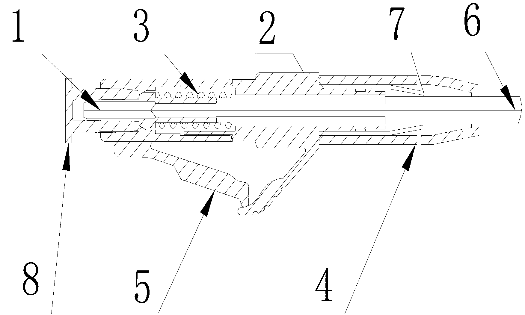
[0017] refer to figure 1 , figure 2 , the present invention includes a ferrule 1, a connector 2, a spring 3, a boot 4, a housing 5, a bare optical fiber 6 and a crimping ring 7, the connector 2 is provided with a buckle, and the head of the connector 2 is connected to the housing 5 , the shell 5 passes through the ferrule 1 and is stuck on the buckle, the tail end of the connector is provided with a riveting part, the tail end of the connector 2 is connected with the boot 4, and the boot 4 is a hollow cylinder The outer surface of one end shrinks inwardly, the shell 5, the connector 2 and the boot 4 form a cavity, the spring 3 and the ferrule 1 are placed in the cavity, the inner wall of the connector 2 is provided with a boss, and the spring 3 is arranged on the connector 2 On the boss of the inner wall, one end of the bare optical fiber 6 of the optical c...


PUM


Abstract

The invention relates to an optical fiber connecting device, in particular to an LC-type short-tail heat-shrink-tube-free optical fiber moving connector which comprises an inserting core, a connecting member, a spring, a tail sleeve, a shell, an optical cable bare fiber and a pressing-connecting ring. The head end of the connecting member is connected with the shell, the tail end of the connecting member is connected with the tail sleeve, the shell and the connecting member form a cavity, the spring and the inserting core are disposed in the cavity, one end of the optical cable bare fiber is fixed to the inserting core while the other end of the same penetrates the cavity, a riveting-pressing member is arranged at the tail end of the connecting member, the pressing-connecting ring is arranged on the riveting-pressing member at the tail end of the connecting member, the tail sleeve is sleeved outside the pressing-connecting ring, the tail sleeve is in the shape of a hollow cylinder, and the outer surface of one end of the tail sleeve shrinks inwards. The LC-type short-tail heat-shrink-tube-free optical fiber moving connector is simple in structure, small in occupied space and convenient to mount and use, and shedding can be effectively prevented.

Description


Claims


Application Information

Patent Timeline
Owner 上海永鼎光电子技术有限公司
Learn More