
washing machine detergent box

A technology for detergent boxes and washing machines, which can be applied to other washing machines, washing devices, textiles and paper making, etc., and can solve the problems of small pulling force, wear of raised parts, poor hand feeling, etc.

Active Publication Date: 2016-09-14
BSH ELECTRICAL APPLIANCES JIANGSU
View PDF5 Cites 0 Cited by
  • Summary
  • Abstract
  • Description
  • Claims
  • Application Information

AI Technical Summary

Problems solved by technology

However, there are following problems in this detachment prevention structure: after repeated operations of inserting and pulling out the detergent box, the raised part on one side of the detergent box will be severely worn, causing the detergent box to be inserted and unable to be clamped and easily It falls off automatically; in addition, different products have different pulling forces when they are pulled out of the detergent box by force, some have high pulling force, some have low pulling force, and have poor hand feeling

Method used


Image

  • washing machine detergent box
  • washing machine detergent box
  • washing machine detergent box

Examples


Embodiment approach 1

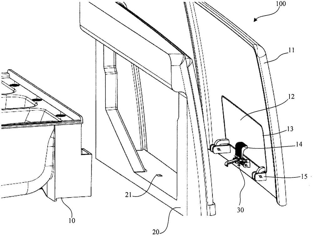
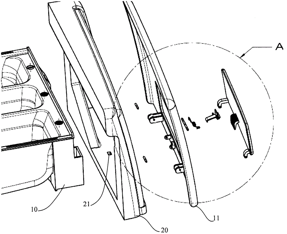
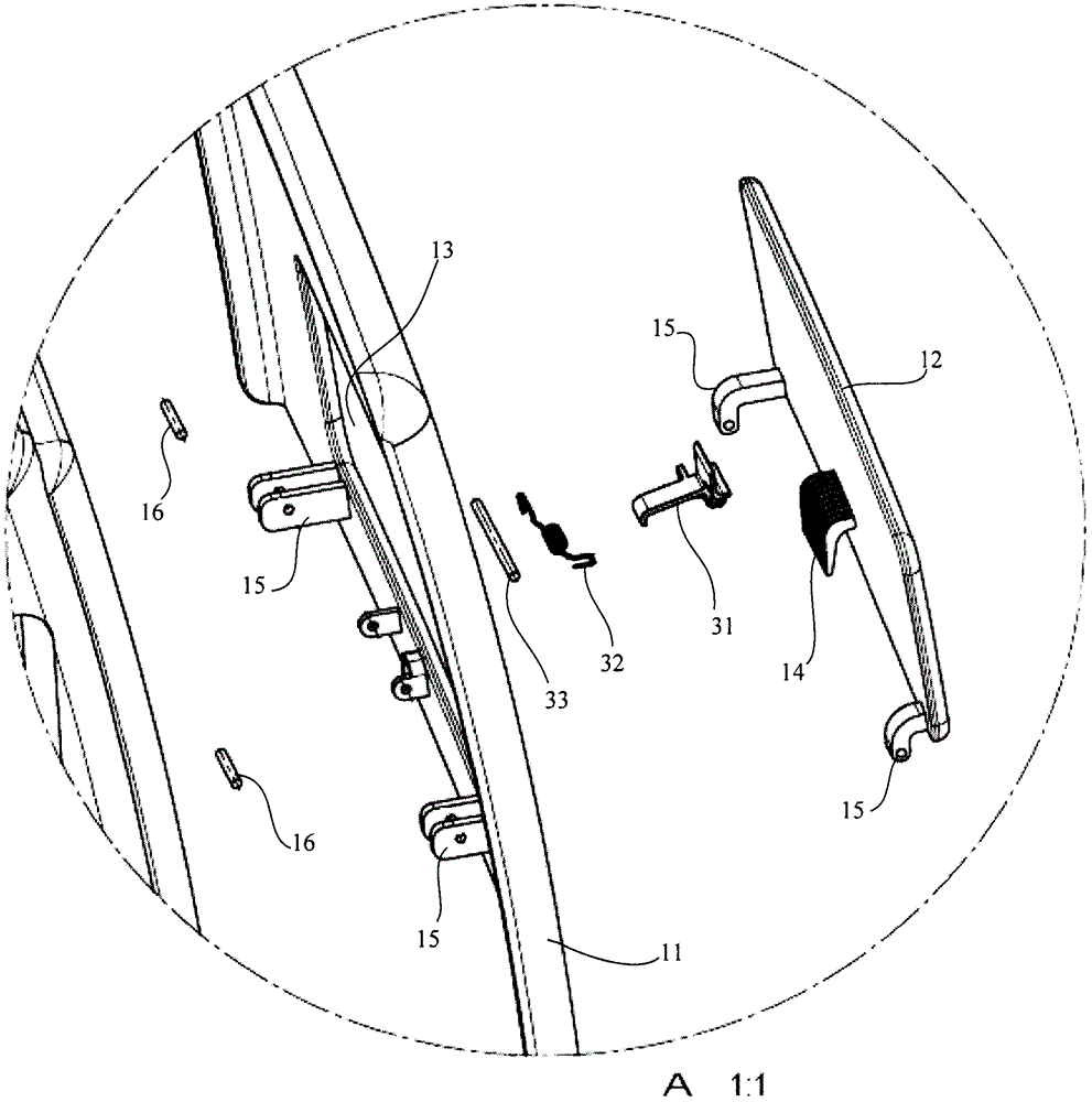
[0028] attached figure 1 It is an exploded view of the structure of the detergent box 100 and the washing machine shell 20, with figure 2 is attached figure 1 explosion diagram of the structure. Such as figure 1 , 2 As shown, the detergent box 100 includes a box body 10 for putting detergent, a front panel 11 is formed at the front end of the box body 10, and an opening 13 for hand insertion is provided on the front panel 11 for opening and closing the opening. 13, the inside and outside flip-type cover plate 12 is hinged on the inner side wall of the front panel 11 through the hinge 15, and the hinge 15 is provided with a rotary pin 16, and the inside and outside flip-type cover plate 12 realizes the inside and outside flip through the hinge 15 and the rotary pin 16, thereby The effect of opening and closing the front panel opening 13 is achieved. A locking device 30 is provided on the inner side wall of the front panel 11 , and when the detergent box is inserted into t...

Embodiment approach 2

[0032] attached Figure 5 is an exploded view of the structure of the second embodiment of the present invention. The difference from the above-mentioned embodiment is that the movable cover plate 12 adopts a sliding type up and down. The up and down sliding cover plate 12 is located on the inside of the opening 13 of the front panel 11, and the left and right sides of the opening 13 are provided with up and down slideways 17, and the up and down sliding type cover plate 12 is slid in the slideway 17. A pick (not shown in the figure) is provided on the outer side of the cover plate 12 , and the locking device 30 is arranged on the inner side wall of the cover plate 12 which slides up and down. attached Figure 6 It is a state diagram in which the detergent box 100 is inserted into the washing machine and locked. Such as Figure 6 As shown, the locking device 30 can be a fixed buckle provided on the inner side wall of the up and down sliding cover 12 , and moves up and down...


PUM


Abstract

The invention discloses a detergent box (100) of a washing machine, comprising a box body (10) for putting detergent in, a front panel (11) formed at the front end of the box body (10), and a front panel (11) on the front panel (11) is provided with the opening (13) that can be stretched into by hand, is used for opening and closing the movable cover plate (12) of described opening (13), the front panel (11) or movable cover plate (12) A locking device (30) linked with the movable cover (12) is provided on the inner side wall. When the detergent box (100) is inserted into the washing machine, the locking device (30) can be locked in the shell (20) of the washing machine. ); the movable cover (12) is used to unlock the locking device (30) when driving the locking device (30). Therefore, the problems of wear and tear and automatic detachment from the washing machine existing in the existing detergent box during insertion or pulling out of the washing machine are solved.

Description

【Technical field】 [0001] The invention relates to a detergent box for a washing machine. 【Background technique】 [0002] The washing machine is a device that cleans the laundry through a series of washing processes such as washing, cleaning, dehydration, and drying in order to remove the dirt stuck to the clothes, quilt covers, etc. in the drum under the action of water and detergent. The washing machine generally includes: a shell, which forms an appearance, and has a laundry input port on one side; a washing machine door, installed on the shell, for opening and closing the laundry input port; a washing tub, placed in the washing machine body, for filling Laundry water; a drum, rotatably installed in the washing tub, for containing laundry; and a motor, for rotating the above drum. In addition, the washing machine is generally provided with a detergent box with two or three independent chambers. [0003] One side of the detergent box in the prior art is provided with a pr...

Claims


Application Information

Patent Timeline
Patent Type & Authority Patents(China)
IPC IPC(8): D06F39/02
CPCD06F39/02
Inventor 李巍仲阿芳姚伯礼
Owner BSH ELECTRICAL APPLIANCES JIANGSU
Learn More