
Container self-loading truck

A technology for containers and loading and unloading vehicles, applied in the direction of vehicles with cranes, etc., can solve problems affecting operation speed and efficiency, human resource occupancy efficiency, and high efficiency requirements, so as to reduce the possibility of electric sparks and static electricity, and reduce resource investment. , the effect of reducing the risk factor

Active Publication Date: 2015-11-04
CHONGQING BAORUN MINING MACHINERY MFG
View PDF5 Cites 0 Cited by
  • Summary
  • Abstract
  • Description
  • Claims
  • Application Information

AI Technical Summary

Problems solved by technology

[0002] At present, the main function of the domestic coal mine explosion-proof diesel engine trackless rubber-tyred vehicle container self-loading truck (hereinafter referred to as the container self-loading truck) is to realize the lifting and transportation of the container in the underground. The traditional container self-loading truck generally adopts a single-arm crane structure. , when the cargo is transferred from the ground to the car body, it can only make a circular movement around the single-arm suspension seat. When the box is in place, multiple people are required to repeatedly operate the steering of the boom and the expansion and contraction of the single arm. Therefore, It leads to a huge occupation of human resources and low efficiency. The underground transfer and transportation of containers in mines have high requirements for efficiency. The traditional container self-loading and unloading trucks have greatly affected the operation speed and efficiency due to their own design defects and insufficiencies. This technology The problem will affect such coal mining enterprises for a long time. At the same time, there is no mature product that can solve this kind of problem in the existing market. Therefore, it is a technical problem that needs to be solved urgently.

Method used


Image

  • Container self-loading truck
  • Container self-loading truck
  • Container self-loading truck

Examples


Embodiment Construction

[0020] In order to make it easy to understand the technical means, creative features, objectives and effects achieved by the present invention, the present invention will be further explained below in conjunction with specific drawings. Unless otherwise specified, the front, rear, left, and right sides mentioned in the present invention are all referred to the front view of the container self-loading and unloading vehicle.

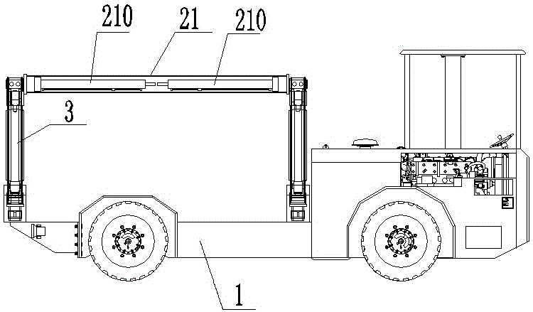
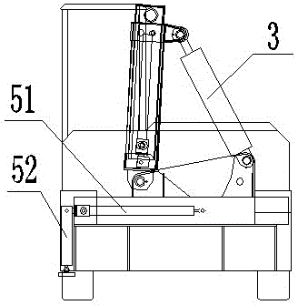
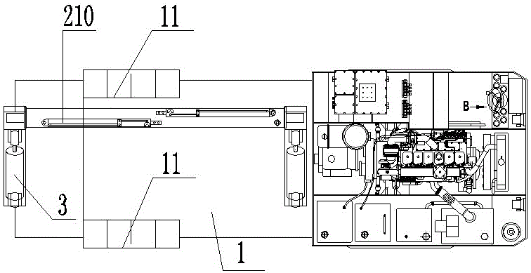
[0021] Example: such as Figure 1-4 As shown, a self-loading and unloading container truck includes a carriage 1, and a loading and unloading device is arranged on the carriage 1. The loading and unloading device includes a gantry arranged along the length of the carriage, which has a gantry beam 21 (a gantry beam and a gantry column The top connection, specifically, the gantry beam is connected with the top of the gantry inner column mentioned below) and the second gantry column 22. The bottom of the gantry column 22 is hinged to the carriage 1, and the gant...


PUM


Abstract

The invention discloses a self-loading and unloading truck for a container. The self-loading and unloading truck comprises a compartment, wherein a loading and unloading device is arranged on the compartment and comprises a portal frame arranged in the length direction of the compartment; the portal frame is provided with a portal frame cross beam and two portal frame columns of which the bottoms are hinged to the compartment; a portal frame oscillating oil cylinder is arranged on one side of the portal frame columns; the cylinder body of the portal frame oscillating oil cylinder is hinged to the compartment; the piston rod of the portal frame oscillating oil cylinder is hinged to the portal frame columns; hoisting oil cylinders are respectively arranged at the two ends of the portal frame cross beam; a hoisting structure is arranged on the piston rods of the hoisting oil cylinders; a support structure is arranged on the goods loading and unloading side of the compartment and provided with at least two support frame sliding oil cylinders; a support oil cylinder is arranged on the piston rod of the support frame sliding oil cylinder. After the portal frame type hoisting device is arranged on the self-loading and unloading truck for the container, the limitation that a traditional self-loading and unloading truck for the container requires multiple persons for coordinated operation is changed, human resources are saved, resource investment is reduced for coal mine enterprises, and the goods turnover efficiency is improved.

Description

Technical field [0001] The invention relates to a loading and unloading vehicle, in particular to a container self-loading and unloading vehicle. Background technique [0002] At present, the main function of the domestic coal mine explosion-proof diesel engine trackless rubber tire container self-loader (hereinafter referred to as the container self-loader) underground is to realize the lifting and transportation of containers. The traditional container self-loader generally adopts a single-arm crane structure. , When the cargo is transferred from the ground to the car body, it can only make a circular rotation around the single-arm crane base. When the box body is in place, multiple people are required to repeatedly operate the steering of the boom and the telescopic operation of the single arm. This results in a huge occupation of human resources and low efficiency. The transfer and transportation of containers in underground mines have high requirements for efficiency. Due to...

Claims


Application Information

Patent Timeline
Patent Type & Authority Patents(China)
IPC IPC(8): B60P1/54
Inventor 刘风录王继民史金彪于洪吉毕东平廖涛
Owner CHONGQING BAORUN MINING MACHINERY MFG
Learn More