Optical network unit (ONU) optical module

An optical module and optical fiber technology, applied in optical fiber transmission, electromagnetic wave transmission systems, electrical components, etc., can solve the problem of inability to monitor optical splitter branch fiber lines

Inactive Publication Date: 2013-09-11
SOURCE PHOTONICS CHENGDU
View PDF4 Cites 2 Cited by
  • Summary
  • Abstract
  • Description
  • Claims
  • Application Information

AI Technical Summary

Problems solved by technology

[0006] If the above-mentioned OLT system and ONU optical modules are used to arrange the network, the OTDR function of the OLT optical module can only monitor the main fiber between the OLT and the optical splitter, and the optical fiber between the optical splitter and the ONU optical module The branch optical fiber line can only collect noise, so the branch optical fiber line between the optical splitter and the ONU cannot be monitored

Method used


Image

  • Optical network unit (ONU) optical module

Examples


Embodiment Construction

[0025] The present invention will be further described in detail below in conjunction with test examples and specific embodiments. However, it should not be understood that the scope of the above subject matter of the present invention is limited to the following embodiments, and all technologies realized based on the content of the present invention belong to the scope of the present invention.

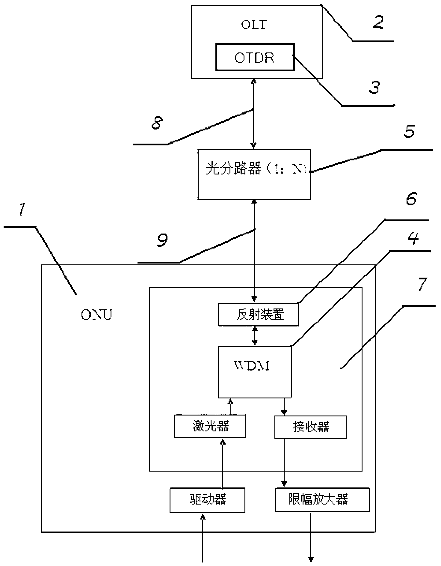
[0026] Such as figure 1 As shown, an ONU optical module 1, the ONU optical module 1 includes an optical device 7, the optical device 7 includes a laser, WDM4, a receiver, and the optical device 7 also includes a reflection device 6;

[0027] The laser is connected to the WDM4, the WDM4 is connected to the reflection device 6, and the WDM4 is connected to the receiver;

[0028] The laser is used to generate and send out optical signals, the WDM4 is used to separate optical signals of different wavelengths, and the receiver is used to receive the optical signals;

[0029] The reflect...


PUM


Abstract

An optical network unit (ONU) optical module comprises an optical device. The optical device comprises a laser, a wavelength division multiplexer (WDM), a receiver and a reflection device, wherein the laser is connected with the WDM, and the WDM is connected with the reflection device and the receiver. The laser is used for generating and sending optical signals. The WDM is used for separating the optical signals with different wavelengths. The receiver is used for receiving the optical signals. The reflection device reflects optical pulse signals generated by an optical time domain reflectometer (OTDR). The OTDR generates the optical pulse signals and sends the optical pulse signals to a main optical fiber located between an optical line terminal (OLT) and an optical divider and branch optical fibers located between the optical divider and the ONU optical module. The reflection device arranged at the ONU optical module end reflects the optical pulse signals generated by the OTDR, and the OTDR receives the optical pulse signals reflected back from the reflection device to detect the main optical fiber and the branch optical fibers.

Description

technical field [0001] The invention relates to an ONU optical module. Background technique [0002] The invention relates to an optical device network and optical fiber testing technology. Passive optical network refers to an optical distribution network (ODN) that does not contain any electronic devices and electronic power supplies. The ODN is composed of passive devices such as optical splitters (Splitter) composition. A passive optical network includes an optical line terminal (OLT) installed in the central control station, and a batch of supporting optical network units (ONU) installed in the user's premises. The optical distribution network (ODN) between the OLT and the ONU includes optical fibers and passive optical splitters or couplers. Optical Time Domain Reflectometry (OTDR) is to monitor the performance of optical fiber to judge events such as fiber length, fiber attenuation, fiber splicing point, connector or fiber break location. The optical pulse signal is...

Claims


Application Information

Patent Timeline
Patent Type & Authority Applications(China)
IPC IPC(8): H04B10/071H04B10/25
Inventor 仵允贤赵福强陈硕许远忠
Owner SOURCE PHOTONICS CHENGDU
Why Eureka
Try Eureka