Projection method and electronic device
An electronic device and projection technology, applied in the direction of instruments, projection devices, optics, etc., can solve the problems of large size, affecting viewing effect, blocking the viewer's line of sight of projection, etc.
- Summary
- Abstract
- Description
- Claims
- Application Information
AI Technical Summary
Problems solved by technology
Method used
Image

Examples
Embodiment 1
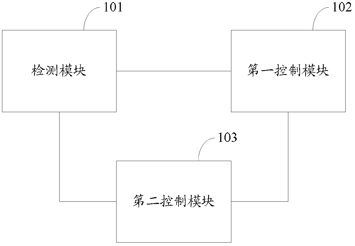
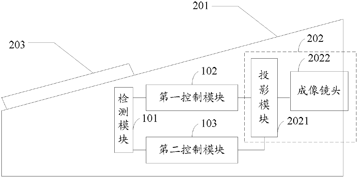
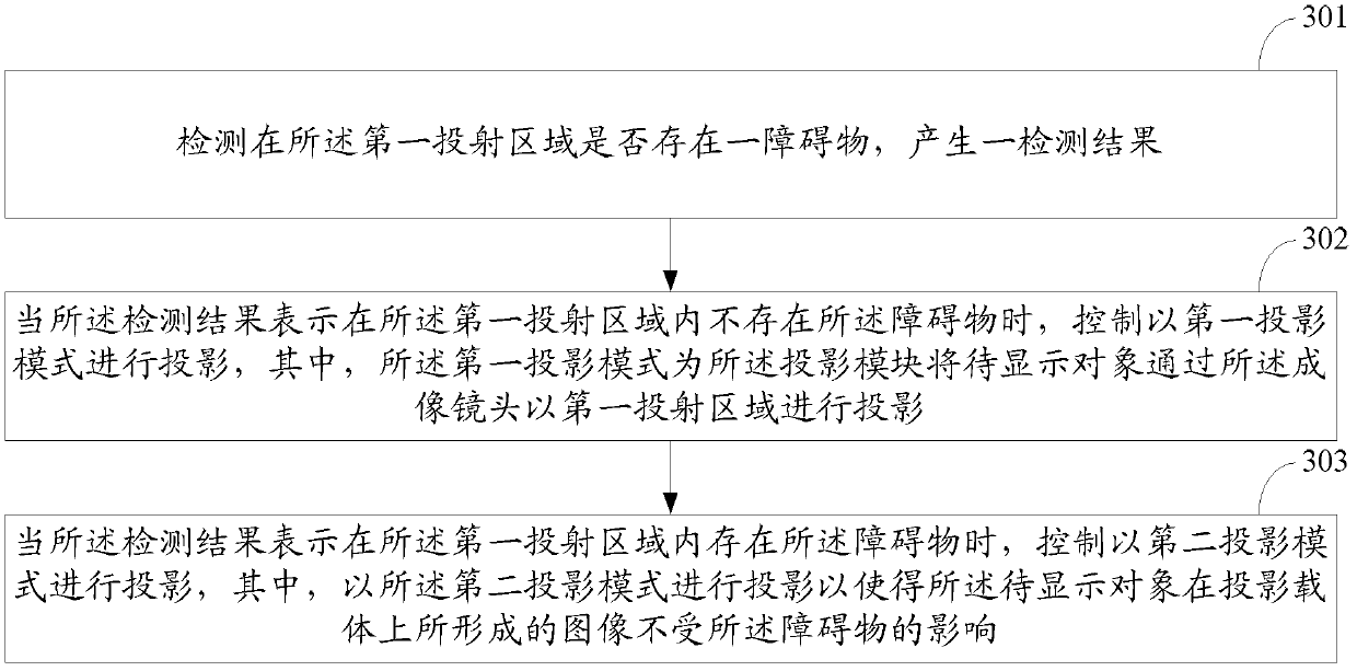
[0057] The electronic device is placed on the first edge of the table. The electronic device includes a housing 201 and a main body 202. The main body 202 includes a projection module 2021 and an imaging lens 2022. The electronic device also includes an input device 203. 203 is provided separately from the electronic device. The user is located on the second edge of the table opposite to the first edge, and the input device 203 is located on the user side. When projection is needed, the detection module 101 detects that there is no obstacle in the first projection area, and the first control module 102 controls the electronic device to perform projection in the first projection mode, that is, controls the projection module In 2021, the object to be displayed is projected in the first projection area through the imaging lens 2022.
Embodiment 2
[0059] The electronic device is placed on the first edge of the table. The electronic device includes a housing 201 and a main body 202. The main body 202 includes a projection module 2021 and an imaging lens 2022. The electronic device also includes an input device 203. 203 is not separated from the electronic device, and the input device 203 is located on the upper end surface of the housing 201 close to the rear end of the housing 201. When projection is required, the detection module 101 detects that there is an obstacle in the first projection area. In the embodiment of the present invention, the obstacle is one placed on the supporting surface for supporting the electronic device. Cup, the supporting surface in the embodiment of the present invention is a desktop. Then the second control module 103 controls the electronic device to perform projection in the second projection mode according to the detection result of the detection module 101, that is, controls the projecti...
Embodiment 3
[0061] The first stage: The electronic device is placed on the first edge of the table. The electronic device includes a housing 201 and a main body 202. The main body 202 includes a projection module 2021 and an imaging lens 2022. The electronic device also includes an input device 203 The input device 203 is not separated from the electronic device, and the input device 203 is located on the upper end surface of the housing 201 close to the rear end of the housing 201. When projection is needed, the detection module 101 detects that there is no obstacle in the first projection area, and the first control module 102 controls the electronic device to perform projection in the first projection mode, that is, controls the projection module In 2021, the object to be displayed is projected in the first projection area through the imaging lens 2022.
[0062] The second stage: during the projection process, a user stands in the first projection area, and the detection module 101 detect...
PUM
 Abstract
Description
Claims
Application Information
 - R&D
- Intellectual Property
- Life Sciences
- Materials
- Tech Scout
- Unparalleled Data Quality
- Higher Quality Content
- 60% Fewer Hallucinations
Browse by: Latest US Patents, China's latest patents, Technical Efficacy Thesaurus, Application Domain, Technology Topic, Popular Technical Reports.
© 2025 PatSnap. All rights reserved.Legal|Privacy policy|Modern Slavery Act Transparency Statement|Sitemap|About US| Contact US: help@patsnap.com