
Card rail fiber storage tray

A fiber storage tray and fiber storage technology, which is applied in the direction of fiber mechanical structure, etc., can solve the problems that the storage function cannot be reserved in advance in limited space, and the number of optical fibers and optical fibers cannot be determined in advance, so as to save equipment installation space and optical fiber routing specifications. Orderly, flexible and easy installation and disassembly

Active Publication Date: 2015-12-02
南京科羿康光电设备有限公司
View PDF6 Cites 0 Cited by
  • Summary
  • Abstract
  • Description
  • Claims
  • Application Information

AI Technical Summary

Problems solved by technology

The industrial machine (screen) cabinet is mainly used for various equipment installation and cable routing. It is difficult to determine the optical fiber and the number of optical fibers involved in advance, and it is impossible to reserve the fiber storage function in a limited space. Optical fiber storage device with flexible adjustment of the number of optical fibers on site

Method used


Image

  • Card rail fiber storage tray
  • Card rail fiber storage tray
  • Card rail fiber storage tray

Examples


Embodiment Construction

[0038] The present invention will be further described below in conjunction with the accompanying drawings and embodiments.

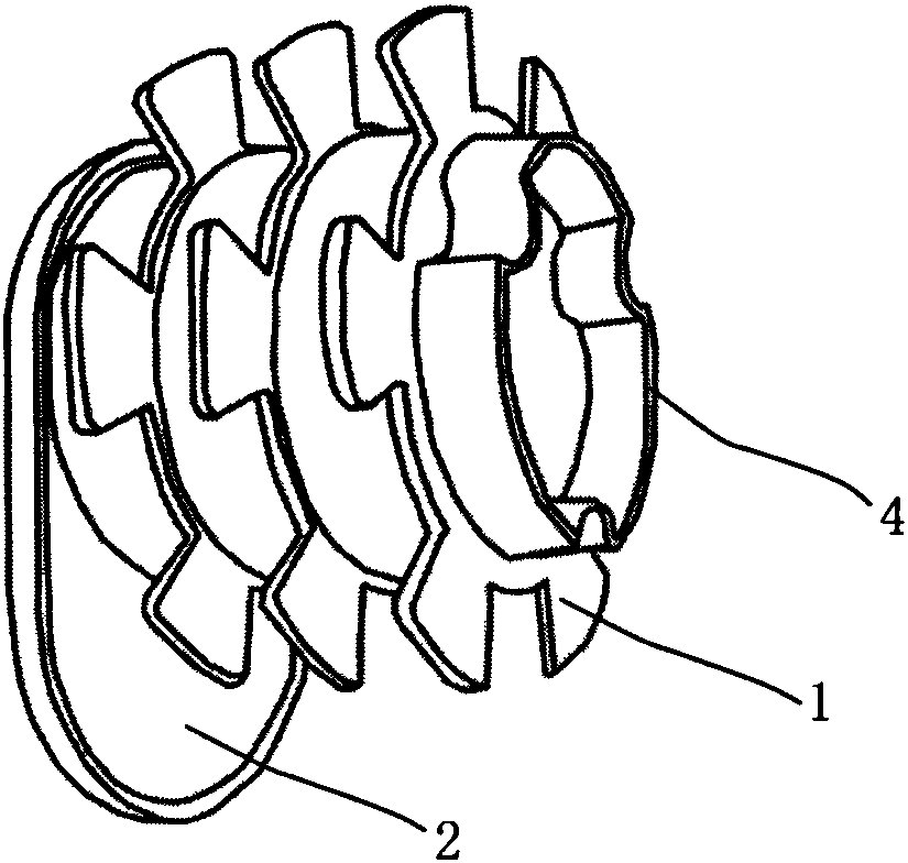
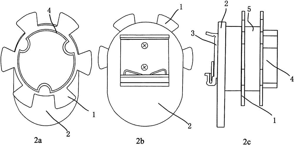
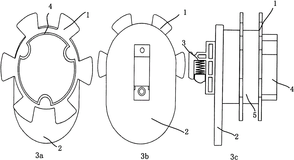
[0039] figure 1 It is a schematic diagram of the rail-type fiber storage tray of the present invention, and there are 3 types of clips; figure 2 It is a schematic diagram of the structure of the U-track fiber storage tray; image 3 is a schematic diagram of the structure of the G-track fiber storage tray; Figure 4 It is a schematic diagram of the structure of the U / G rail universal fiber storage tray; Figure 5 It is a schematic diagram of the structure of the fiber storage unit.

[0040] See Figure 1 to Figure 5 The rail-type fiber storage tray provided by the present invention includes a fiber storage unit 1, a base 2, and a clip 3. The fiber storage unit 1 is installed on the base 2, and the front of the base 2 is provided with a third protrusion (not shown in the figure), The size of the third protrusion matches the size of the second protru...


PUM


Abstract

The invention discloses an optical fiber storage device, namely, a rail clamping type optical fiber storage plate. The rail clamping type optical fiber storage plate comprises an optical fiber storage unit, a base and a clamping piece, wherein the optical fiber storage unit is installed on the base, the number of the optical fiber storage unit is at least one, the clamping piece is installed on the back face of the base, and the clamping piece is a U track clamping piece or a G track clamping piece or a U / G track universal clamping piece. A clamping foot of the clamping piece is used for being fixed on a 35mm U-shaped guide rail or a 35mm G-shaped DIN guide rail, and the rail clamping type optical fiber storage plate is conveniently installed and detached. The rail clamping type optical fiber storage plate is mainly used for an industrial machine (screen) cabinet with the DIN guide rail, redundant optical fibers can be arranged, collected and stored, and optical fiber line arrangement of the whole machine cabinet is standardized and orderly. According to the rail clamping type optical fiber storage plate, the number of optical fiber storage units can be flexibly increased or decreased according to the number of optical fibers stored by the machine (screen) cabinet on spot, operation is flexible, simple and convenient to conduct, the fault probability produced when equipment is connected with optical fibers can be reduced, the maintenance level is improved, and maintenance cost is reduced.

Description

technical field [0001] The invention relates to a fiber storage device, in particular to a rail-type fiber storage tray which can be installed in an industrial cabinet. Background technique [0002] As more and more industrial sites use optical fiber communication, it is necessary to implement effective management of optical fiber routing, including requiring that redundant optical fibers after equipment connections be stored and stored without damage. Since the industrial machine (screen) cabinet has no optical fiber storage mechanism, redundant optical fibers are often hung on the side of the cabinet or stuffed into the wiring trough, which is likely to cause optical fiber failure and also bring inconvenience to maintenance work. [0003] The optical fiber distribution frame widely used in telecommunications, radio and television and other fields is a full-featured optical fiber management device, but it is not suitable for industrial sites. The industrial machine (screen...

Claims


Application Information

Patent Timeline
Patent Type & Authority Patents(China)
IPC IPC(8): G02B6/44
Inventor 虞宁生
Owner 南京科羿康光电设备有限公司
Learn More