Improved cloth rolling machine structure

A cloth winding machine and frame technology, which is applied in the direction of winding strips, thin material processing, transportation and packaging, etc., can solve the problems of increased cost of the whole machine, high labor intensity of workers, and large power consumption, so as to simplify the structure, Easy to manufacture, install and maintain

Inactive Publication Date: 2013-09-11
常熟市龙略机电有限公司
View PDF14 Cites 10 Cited by
  • Summary
  • Abstract
  • Description
  • Claims
  • Application Information

AI Technical Summary

Problems solved by technology

[0003] Although the technical schemes not limited to the above-mentioned cloth rolling machines have corresponding technical effects, there are the following technical problems: one is that in the process of rolling cloth, the cloth, that is, the cloth, inevitably has a deviation from left to right. Therefore, the end of the rolled-up cloth roll is uneven, that is, a serious gyro phenomenon occurs; secondly, due to the complex structure of the cloth guide roller driving mechanism, usually the upper and lower cloth guide rollers and The cloth expansion mechanism is driven by its own power, so it not only consumes a lot of electric energy, but also causes troubles in manufacturing, installation and maintenance, and leads to an increase in the cost of the whole machine
Although this processing method can make the two ends of the cloth rolled into a cylindrical body tend to be even, objectively there are the following problems: First, because it is necessary to arrange a special person to correct the deviation of the cloth, it causes valuable labor Waste of resources; secondly, because the workers need to pull the fabric manually, the labor intensity of the workers is high; thirdly, due to the manual correction, the leveling effect of the two ends of the fabric roll is usually difficult to achieve a satisfactory level, Because human error correction is often changed due to individual differences, experience differences, responsibility differences and emotional changes of workers, etc.
Again, for the problem of the complex structure of the cloth guide roller driving mechanism, there is no technical revelation that can be solved in the currently disclosed patents and non-patent literature

Method used


Image

  • Improved cloth rolling machine structure
  • Improved cloth rolling machine structure

Examples


Embodiment

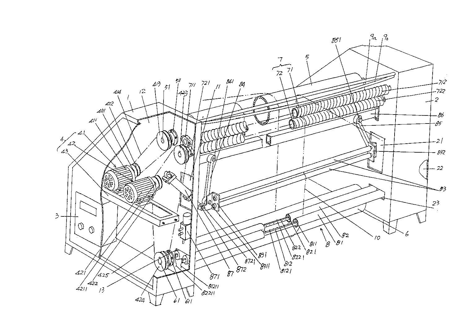
[0021] See figure 1 , a first rack wall panel 1 and a second rack wall panel 2 are given, the first and second rack wall panels 1, 2 are arranged facing each other and connected together in the state of use, the first 1. The specific structures of the second rack wall panels 1 and 2 are substantially the same, and each is formed with a wall panel cavity, that is, the first frame wall panel 1 forms a first wall panel cavity 12, and the second frame wall The panel 2 forms a second panel cavity 22 . On the wall body on the side of the first frame wallboard 1 towards the second frame wallboard 2, there is a first relief chamber 11 communicated with the first wallboard cavity 12; and on the second frame wallboard 2 A second relief chamber 21 communicating with the second wallboard cavity 22 is provided on the wall facing the side of the first frame wallboard 1, and the first and second relief chambers 11 and 21 correspond to each other.

[0022] An electrical control box 3 is pro...


PUM


Abstract

The invention discloses an improved cloth rolling machine structure and belongs to the technical field of knitting machinery. The improved cloth rolling machine structure comprises a first frame wallboard, a second frame wallboard, an electric control cabinet, a cloth guiding roller driving mechanism, an upper cloth guiding roller, a lower cloth guiding roller and a cloth expanding mechanism, wherein the first frame wallboard and the second frame wallboard are arranged face to face, the electric control cabinet is arranged on the first frame wallboard or the second frame wallboard, the cloth guiding roller driving mechanism is in electric control connection with the electric control cabinet, the upper cloth guiding roller is supported above the position between the first frame wallboard and the second frame wallboard, the lower cloth guiding roller is supported below the position between the first frame wallboard and the second frame wallboard, and the cloth expanding mechanism is arranged above the position between the first frame wallboard and the second frame wallboard. The improved cloth rolling machine structure is characterized by further comprising a deviation detecting and correcting mechanism which is arranged between the first frame wallboard and the second frame wallboard, the cloth guiding roller driving mechanism comprises an upper cloth guiding roller driving device, a lower cloth guiding roller driving device and a mounting base, the upper cloth guiding roller driving device comprises a first motor, a first transmission wheel, a second transmission wheel and a first transmission belt, and the lower cloth guiding roller driving device comprises a second motor, a third transmission wheel, a fourth transmission wheel, a fifth transmission wheel and a second transmission belt. The improved cloth rolling machine structure is energy-saving, convenient to mount and maintain, and capable of reducing work intensity and guaranteeing two ends of a cloth roll to be abreast without gyroscopic effect.

Description

technical field [0001] The invention belongs to the technical field of needle textile machinery, and in particular relates to a cloth rolling machine with an improved structure. Background technique [0002] The function of the cloth winding machine is to wind the knitted textile fabric completed by the previous process into a cylindrical body. A large amount of technical information about the cloth winding machine can be found in the published Chinese patent documents, such as CN2607354Y (improved type cloth rolling machine), CN2760073Y (cloth rolling mechanism of loom), CN201372136Y (cloth rolling mechanism of a cloth rolling machine), CN201567101U (fabric fabric rolling inspection machine), CN102849492A (cloth rolling machine), CN102417119A (cloth rolling machine) , CN202214037U (cloth rolling machine) and CN202594456U (high-speed cloth rolling machine), etc. [0003] Although the technical schemes not limited to the above-mentioned cloth rolling machines have correspon...

Claims


Application Information

Patent Timeline
Patent Type & Authority Applications(China)
IPC IPC(8): B65H23/198B65H23/26
Inventor 潘熠潘慧潘沁
Owner 常熟市龙略机电有限公司
Why Eureka
Try Eureka