Split scraper assembly and conveying equipment

A conveying equipment and split-type technology, applied in the field of split-type scraper components and conveying equipment, can solve the problems such as the inability to continue to increase the manufacturing length of the scraper conveyor, the inconvenience of scraper disassembly and replacement, and the increase of equipment energy consumption, etc. To achieve the effect of convenient replacement operation, improved carrying capacity, and improved production efficiency

Active Publication Date: 2016-01-20
SANY HEAVY EQUIP CO LTD
View PDF7 Cites 0 Cited by
  • Summary
  • Abstract
  • Description
  • Claims
  • Application Information

AI Technical Summary

Problems solved by technology

It can be seen that the scraper with such a large self-weight will increase the energy consumption of the equipment during the working process
[0006] 2) The disassembly and replacement of the existing scraper is inconvenient and inconvenient to operate
[0007] 3) Due to the weight problem of the existing scraper assembly, the manufacturing length of the current scraper conveyor cannot continue to increase, and a larger type of motor must be replaced. Therefore, this virtually increases the cost of the product

Method used


Image

  • Split scraper assembly and conveying equipment
  • Split scraper assembly and conveying equipment
  • Split scraper assembly and conveying equipment

Examples


Embodiment Construction

[0044] The following will clearly and completely describe the technical solutions in the embodiments of the present invention with reference to the accompanying drawings in the embodiments of the present invention. Obviously, the described embodiments are only some, not all, embodiments of the present invention. Based on the embodiments of the present invention, all other embodiments obtained by persons of ordinary skill in the art without creative efforts fall within the protection scope of the present invention.

[0045] It should be noted that, in the case of no conflict, the embodiments of the present invention and the features in the embodiments can be combined with each other.

[0046] Below in conjunction with accompanying drawing, each preferred embodiment of the present invention is described further:

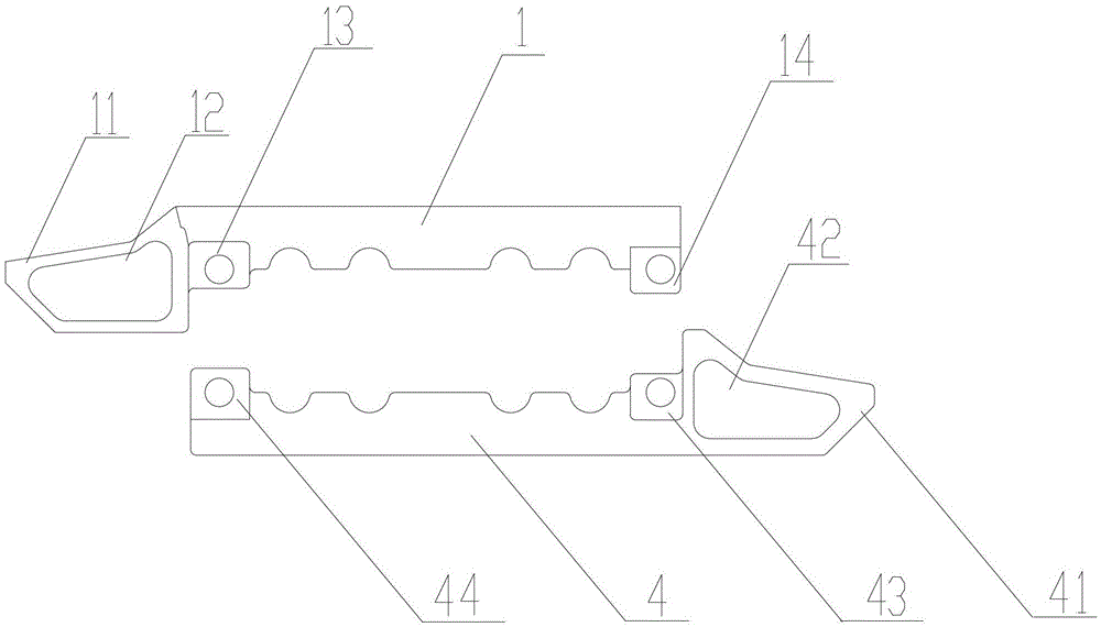
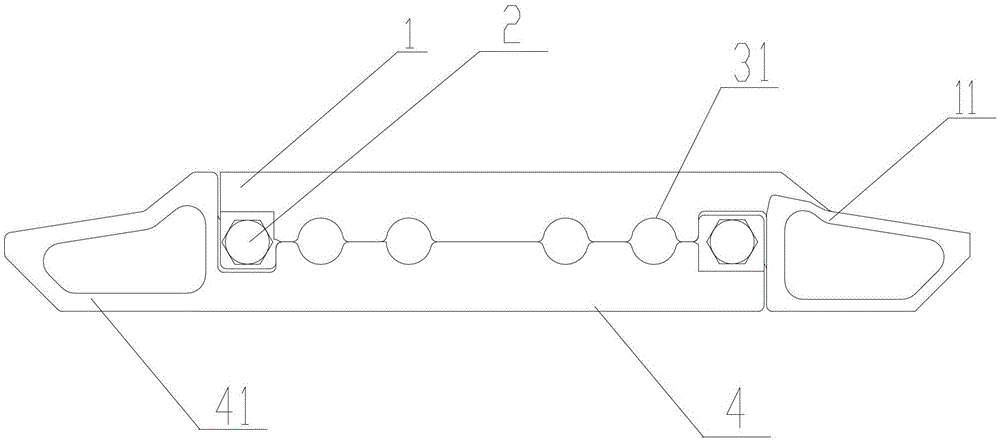
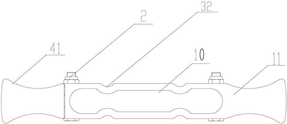
[0047] refer to Figure 1 to Figure 3 , which respectively show the structure of the split scraper assembly of this embodiment, the split scraper assembly includes: u...


PUM


Abstract

The invention discloses a split scraper assembly and conveying equipment. The split scraper assembly includes: an upper scraper body, a lower scraper body, and a connection connecting the upper scraper body and the lower scraper body parts; wherein, the upper end located in front of the head of the upper scraper body is a hollow structure; the lower end located in front of the head of the lower scraper body is a hollow structure. Therefore, the split scraper assembly and conveying equipment of the present invention can reduce no-load energy consumption and improve production efficiency.

Description

technical field [0001] The invention relates to the field of engineering machinery, in particular to a split scraper assembly and conveying equipment provided with the split scraper assembly. Background technique [0002] At present, most scrapers of mine scraper conveyors are made of steel, and are manufactured into a solid bow-back shape by casting one-shot molding process. The scraper of the scraper conveyor is placed in the middle groove of the conveyor, and the scraper is connected in series through the chain. When the scraper conveyor is working, the reducer drives the sprocket, and the sprocket drives the chain and the scraper. The plate moves on the upper surface of the middle plate in the middle trough, scraping the coal from one end of the scraper conveyor to the other end. The scraper and the middle plate of the middle groove are purely sliding friction, because the weight of the current scraper conveyor is relatively heavy, and its friction is relatively large. ...

Claims


Application Information

Patent Timeline
Patent Type & Authority Patents(China)
IPC IPC(8): B65G19/22
Inventor 屈中华万旭马世野
Owner SANY HEAVY EQUIP CO LTD
Why Eureka
Try Eureka