
A Tracking Method Oriented to RFID Passive Tags

A passive tag and tag technology, applied in the field of RFID positioning and tracking, can solve problems such as being inferior to active positioning algorithms, increasing computing time, being deeply affected by obstacles, antenna performance, multipath effects and other factors, achieving accuracy and practicality. Sex-enhancing effect

Active Publication Date: 2016-03-30
祎德科技(北京)有限公司
View PDF5 Cites 0 Cited by
  • Summary
  • Abstract
  • Description
  • Claims
  • Application Information

AI Technical Summary

Problems solved by technology

[0004] According to different principles, the tracking algorithm for RFID passive tags can be divided into time of arrival based on propagation signal, time difference of arrival based on propagation signal, strength of received signal, angle of arrival based on propagation signal and phase of arrival based on propagation signal, etc. There are mainly several types, especially for the positioning of active tags, and there are many applicable methods. Due to the limitations of the use of passive tags, and are deeply affected by factors such as obstacles, antenna performance, and multipath effects, the degree of research is far less than that of active positioning. Algorithms, many of which are only in mathematical calculations, enter more complex mathematical and statistical formulas for calculations to improve accuracy, but this will increase calculation time and increase system load in a mobile background, which is not very practical

Method used


Image

  • A Tracking Method Oriented to RFID Passive Tags
  • A Tracking Method Oriented to RFID Passive Tags
  • A Tracking Method Oriented to RFID Passive Tags

Examples


Embodiment Construction

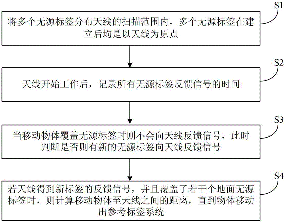
[0027] Such as Figure 1 to Figure 3 As shown, the present invention provides a tracking method for RFID passive tags, including the following steps:

[0028] S1. Distribute multiple passive tags within the scanning range of the antenna. After the multiple passive tags are established, the antenna is the origin.

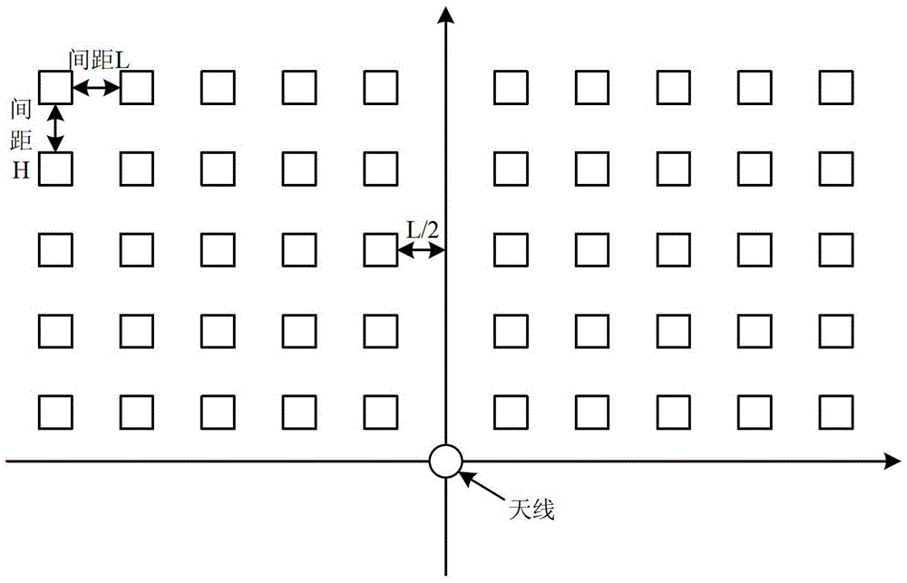
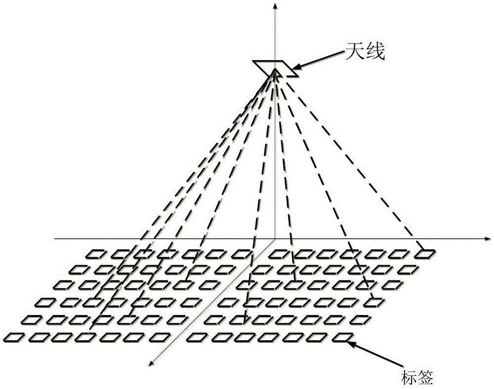
[0029] Specifically, the passive tags are tiled within the scanning range of the antenna in an arrangement of m*n, where m is the number of rows, n is the number of columns, and both m and n are positive integers greater than 1. Passive tags are laid flat on the ground in the corridor facing the antenna.

[0030] S2. After the antenna starts working, record the time of all passive tag feedback signals.

[0031] Specifically, when the antenna is working normally and no moving objects pass by, each passive tag will feed back a signal to the antenna, and start to work after the antenna stably receives the signal fed back by each passive tag.

[0032] Since there are fewer obstac...


PUM


Abstract

The invention provides a tracking method for RFID passive tags. The method comprises the following steps that firstly, a plurality of passive tags are distributed in a scanning range of an antenna, and the antenna serves as an original point of the passive tags after the passive tags are established; secondly, after the antenna starts to work, the antenna records the time when all tags feed back signals; thirdly, when a moving object covers the passive tags, the passive tags cannot feed back signals to the antenna, and the situation that whether a new passive tag feeds the signals back to the antenna or not is judged; fourthly, if the antenna obtains the signals fed back by the new tag and the moving object covers a plurality of ground tags, the distance between the moving object and the antenna is calculated until the object moves out of a reference tag system. The moving object with the tags can be tracked, the characteristic that a barrier can stop the passive tags from communicating with the antenna is utilized, reference tags with certain density are arranged by using the passive tags, the position range of the object is zoomed out so that the specific position of the object can be determined, and great improvements are made on expenditure of time, precision and practicality.

Description

Technical field [0001] The invention belongs to the field of RFID positioning and tracking, in particular to a tracking method for RFID passive tags. Background technique [0002] RFID technology, namely radio frequency identification technology, is a high-tech technology that uses electromagnetic waves for non-contact information exchange. It has the characteristics of fast response, low cost, and high security. Generally, an RFID system consists of electronic tags, antennas, readers, background management software, etc. The antenna communicates with the tag through electromagnetic waves, and the internal information of the tag is modulated by the reader and then transferred to the background management software. The operation of business transactions can realize operations such as modification, update, and reading of label information to achieve real-time monitoring and information interaction. In recent years, RFID technology has been widely used in various fields and is one ...

Claims


Application Information

Patent Timeline
Patent Type & Authority Patents(China)
IPC IPC(8): G06K7/00
Inventor 何泾沙王经纬赵斌徐晶
Owner 祎德科技(北京)有限公司
Learn More