
A split type turning and boring machine for on-site machining

A kind of on-site processing and split technology, applied in the field of machinery, can solve the problem that large workpieces cannot be disassembled, processed and transported, and achieve the effect of simple structure

Active Publication Date: 2016-04-27
GUANGZHOU XINCHENG MECHANICAL TECH
View PDF6 Cites 0 Cited by
  • Summary
  • Abstract
  • Description
  • Claims
  • Application Information

AI Technical Summary

Problems solved by technology

[0003] The invention proposes a split-type turning and boring machine for on-site processing, which solves the problem that large workpieces cannot be disassembled, processed and transported in the prior art

Method used


Image

  • A split type turning and boring machine for on-site machining
  • A split type turning and boring machine for on-site machining
  • A split type turning and boring machine for on-site machining

Examples


Embodiment Construction

[0017] The following will clearly and completely describe the technical solutions in the embodiments of the present invention with reference to the accompanying drawings in the embodiments of the present invention. Obviously, the described embodiments are only some, not all, embodiments of the present invention. Based on the embodiments of the present invention, all other embodiments obtained by persons of ordinary skill in the art without creative efforts fall within the protection scope of the present invention.

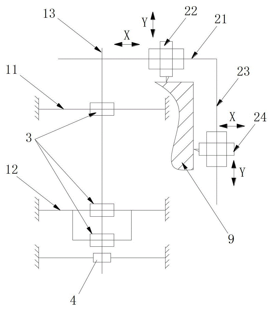
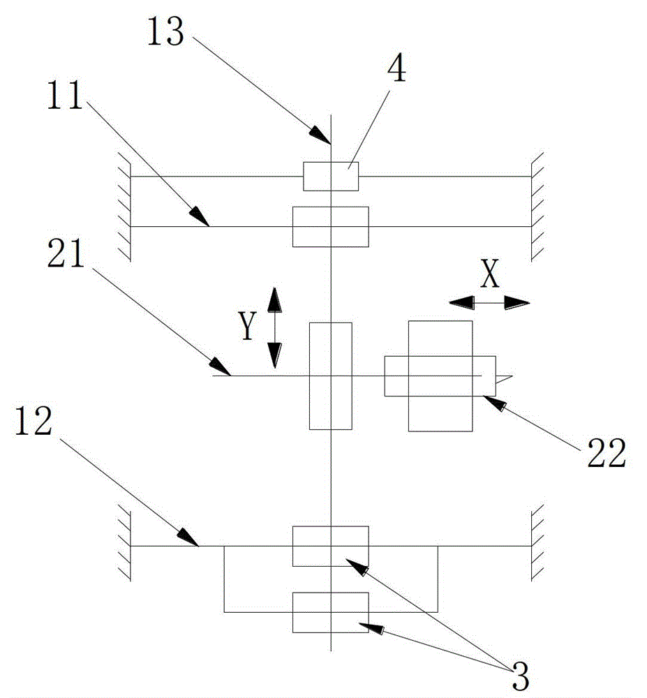
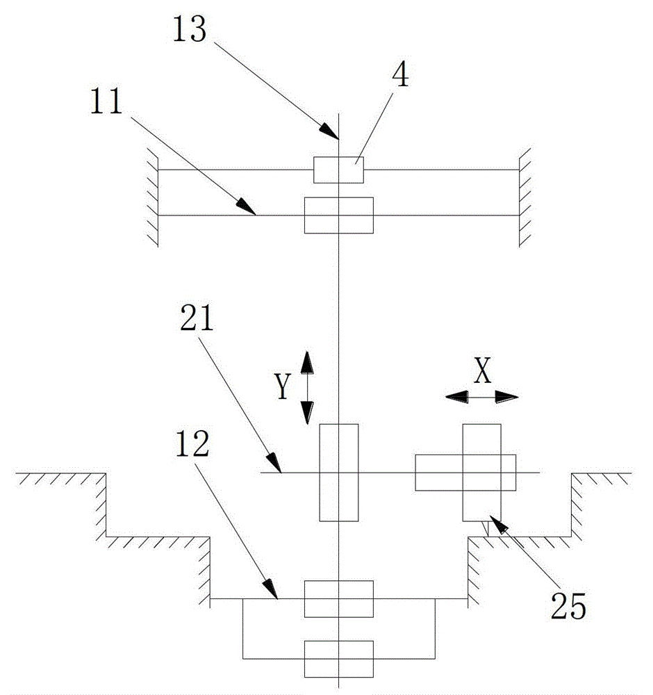
[0018] Such as Figure 1 to Figure 3 The shown on-site processing split turning and boring machine includes a fixed bracket fixed on the workpiece 9 or the reference seat, and the positioning shaft 13 is erected on the fixed bracket; the positioning shaft 13 is detachably provided with a positioning shaft 13 a vertical crossbeam 21, on which a first turning device 22 is slidably arranged, and the first turning device 22 can move horizontally (that is, the X directi...


PUM


Abstract

The invention provides a field processing split type lathe and boring mill which comprises a fixing support fixed on a processing workpiece or a benchmark seat. A positioning shaft is erected on the fixing support, the positioning shaft is provided with a beam perpendicular to the positioning shaft, a first turning device is arranged on the beam in a sliding mode, and the first turning device can move in the horizontal direction and the perpendicular direction. The field processing split type lathe and boring mill can achieve field processing of a large-type device, is simple in lathe structure, can be detachably conveyed to a processing site, is again fixed and assembled on a large-type workpiece to be processed and is disassembled from the workpiece after processing is completed.

Description

technical field [0001] The invention relates to the field of machinery, in particular to a split turning and boring machine for on-site processing. Background technique [0002] At present, the traditional lathe or boring machine is to install the machine tool body on the ground, the workpiece is fixed on the bed body, the machine tool spindle drives the workpiece to rotate, the tool holder moves along the axial or radial direction of the workpiece, and the tool installed on the tool holder performs the Cutting processing, the lathe or boring machine is suitable for the processing of movable small and medium-sized parts. However, in chemical plants, shipyards, steel plants and other enterprises, some workpieces are very large and heavy, difficult to disassemble or divide, and these workpieces cannot be installed on traditional lathes or boring machines for processing; It can also result in enormous transportation costs, or impossible transportation at all. Contents of the...

Claims


Application Information

Patent Timeline
Patent Type & Authority Patents(China)
IPC IPC(8): B23P23/02B23Q9/02
Inventor 张国根
Owner GUANGZHOU XINCHENG MECHANICAL TECH
Learn More