
Upper limb rehabilitation robot

A technology for rehabilitation robots and upper limbs, applied in gymnastics equipment, muscle training equipment, passive exercise equipment, etc., can solve the problems of inconvenience for patients, complex structure, relatively high requirements for control methods and safety, and achieve good rehabilitation Effect, easy to wear, safe and reliable to wear

Active Publication Date: 2013-08-28
SUN YAT SEN UNIV
View PDF4 Cites 30 Cited by
  • Summary
  • Abstract
  • Description
  • Claims
  • Application Information

AI Technical Summary

Problems solved by technology

Although such a method can help patients improve the movement of the hemiplegic side limbs, it also has the following shortcomings: first, physical therapy is usually carried out in a hospital, which is very inconvenient for patients who already have motor dysfunction; second, physical therapy is It is a labor-intensive process. It is difficult for physical therapists to maintain high-intensity and repetitive treatment for a long time. At the same time, there are nearly 10 million stroke patients in my country, and the number of physical therapists is seriously insufficient.
[0004] Most of the existing rehabilitation robots can only provide single-joint or two-degree-of-freedom activities, providing patients with simple linear, curved or plane movements, with limited range of motion and movable joints, and a few multi-degree-of-freedom rehabilitation robots can help patients Activities are carried out in three-dimensional space, but the movement space and action types cannot fully meet the requirements of rehabilitation training. In addition, with the improvement of the degree of freedom of the robot, its structure becomes very complicated, and the requirements for control methods and safety are relatively high.

Method used


Image

  • Upper limb rehabilitation robot
  • Upper limb rehabilitation robot
  • Upper limb rehabilitation robot

Examples


Embodiment approach

[0036] As the third embodiment of the upper limb robot of the present invention: as Figure 5 As shown, the upper limb rehabilitation robot also includes a training mode selection device 20, a storage device 18 storing a rehabilitation training program and a parameter selection device 19 for selecting parameters for the patient, and the training mode includes an active control mode and a passive control mode, The two control methods can be switched to each other. The control device 16 selects according to the training method selected by the patient whether to control the angle and strength of the traction device 10 to pull the rope 6 according to the myoelectric signal collected by the myoelectric signal collection device 17, or to control the angle and strength of the rope 6 pulled by the traction device 10, or to transmit the rope 6 according to the parameter selection device 19. Parameters and the stored rehabilitation training program in the storage device 18 control the a...


PUM


Abstract

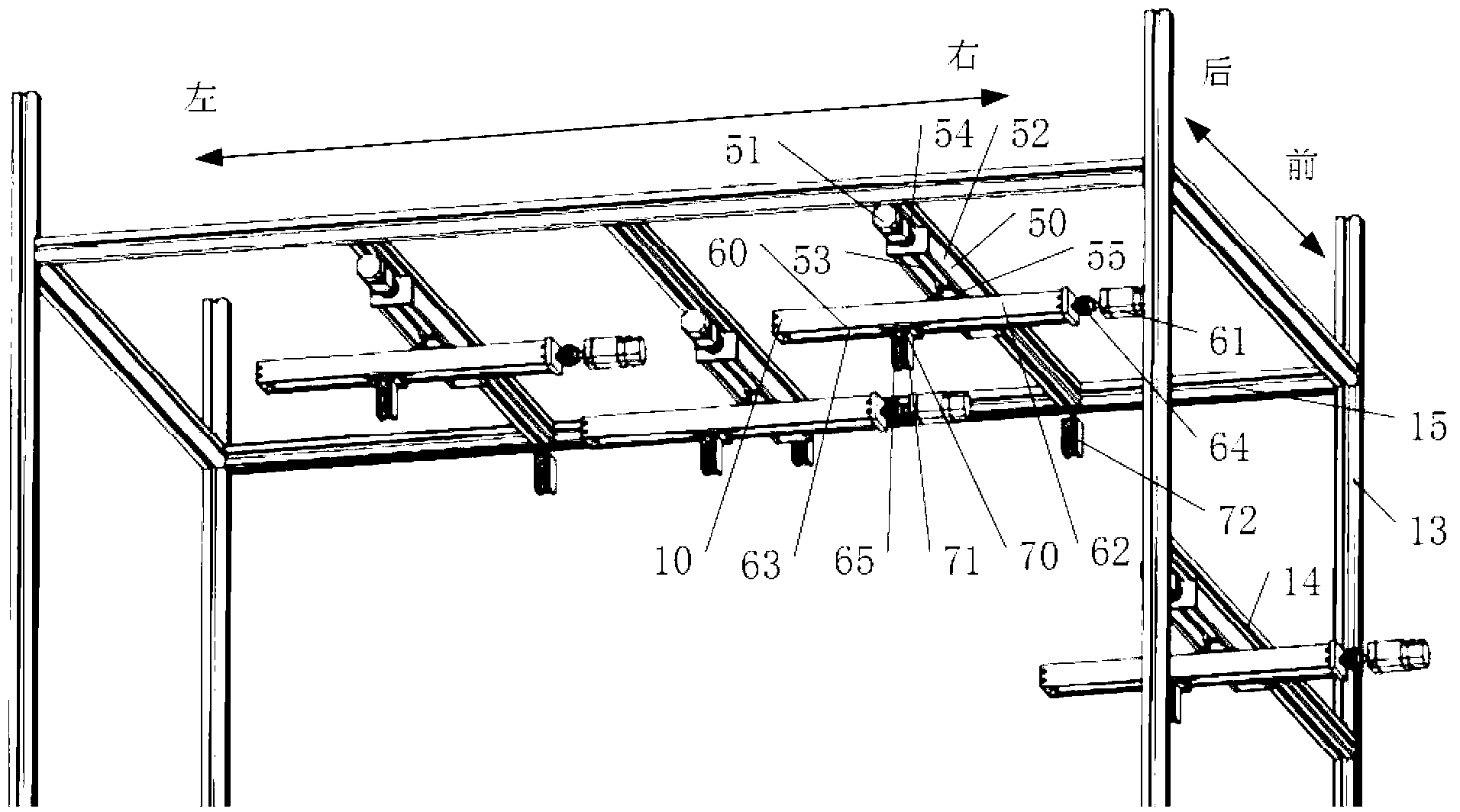
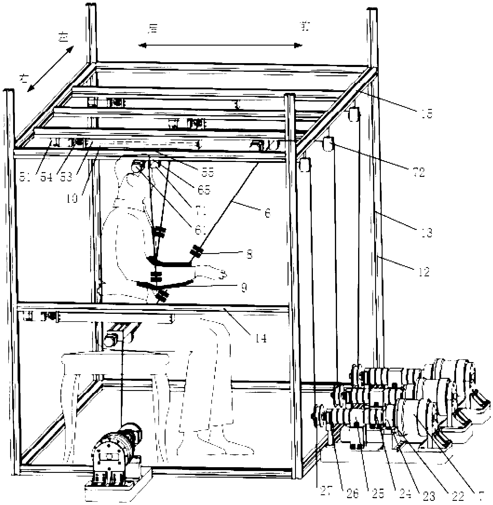
An upper limb rehabilitation robot comprises a support, a plurality of traction devices, a supporting plate, a plurality of ropes and a control device. The support comprises an upright column, a top frame and a cross beam, wherein the top frame is located above the forearm of a patient, and the cross beam is located under the forearm of the patient. The supporting plate is used for the patient to place the forearm. One end of each rope is connected with one of the traction devices, and the other end of each rope is fixed on the supporting plate. The control device is used for controlling the angle and the strength of the traction devices during traction of the ropes. According to the upper limb rehabilitation robot, the control device is used for controlling the angle and the strength of the traction devices during the traction of the ropes so that the patient can be assisted in complicated training actions in a three-dimensional space for shoulder joints and elbow joints of the patient. Therefore, a better rehabilitation effect can be achieved for the patient.

Description

technical field [0001] The invention relates to a medical auxiliary treatment device, in particular to an upper limb rehabilitation robot. Background technique [0002] Cerebrovascular disease is the third leading cause of human death, and more than 2 million people die of stroke every year. In my country, there are 1.2 million to 1.5 million new complete stroke patients every year, and 800,000 to 1 million deaths. Among them, survivors after stroke have unilateral limb motor dysfunction, and the incidence rate of patients in the acute stage is higher, seriously affecting patients. daily behavioral abilities. At present, the clinical rehabilitation method for hemiplegia patients is mainly one-on-one physical therapy for patients by physical therapists. Although such a method can help patients improve the movement of the hemiplegic side limbs, it also has the following shortcomings: first, physical therapy is usually carried out in a hospital, which is very inconvenient for ...

Claims


Application Information

Patent Timeline
IPC IPC(8): A61H1/02A63B23/12A63B24/00
CPCA61H1/0281A61H1/0277A61H2201/018A61H2201/1215A61H2201/1659A61H2230/605A63B21/00178A63B21/00181A63B21/0058A63B21/151A63B21/4021A63B21/4043A63B23/03508A63B23/1209A63B23/1245A63B23/1281A63B24/0087A63B2024/0093A63B2230/605
Inventor 宋嵘杨东静杨锦肖潭袁培江
Owner SUN YAT SEN UNIV
Learn More