
Gas fired radiation emitter with embossed screen

一种辐射发射器、燃气式的技术,应用在燃烧器、气体燃料燃烧器、燃烧方法等方向,达到增强机械抗性、节省刚性增强器件的效果

Inactive Publication Date: 2013-08-21
SOLARONICS
View PDF11 Cites 4 Cited by
  • Summary
  • Abstract
  • Description
  • Claims
  • Application Information

AI Technical Summary

Problems solved by technology

[0011] A known issue with radiant gas burners concerns the efficiency and effectiveness of the radiant screen

Method used


Image

  • Gas fired radiation emitter with embossed screen
  • Gas fired radiation emitter with embossed screen
  • Gas fired radiation emitter with embossed screen

Examples


Embodiment Construction

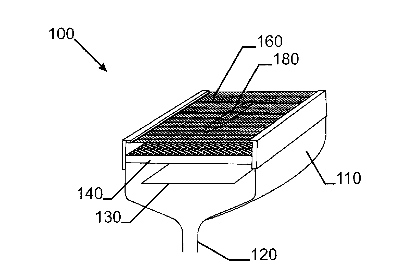
[0049] In an example embodiment, figure 1 The gas-fired radiant emitter 100 includes a body 110 , an inlet 120 for gas and air, a gas distribution plate 130 and a burner plate 140 . The radiant screen 160 has protrusions 180 .

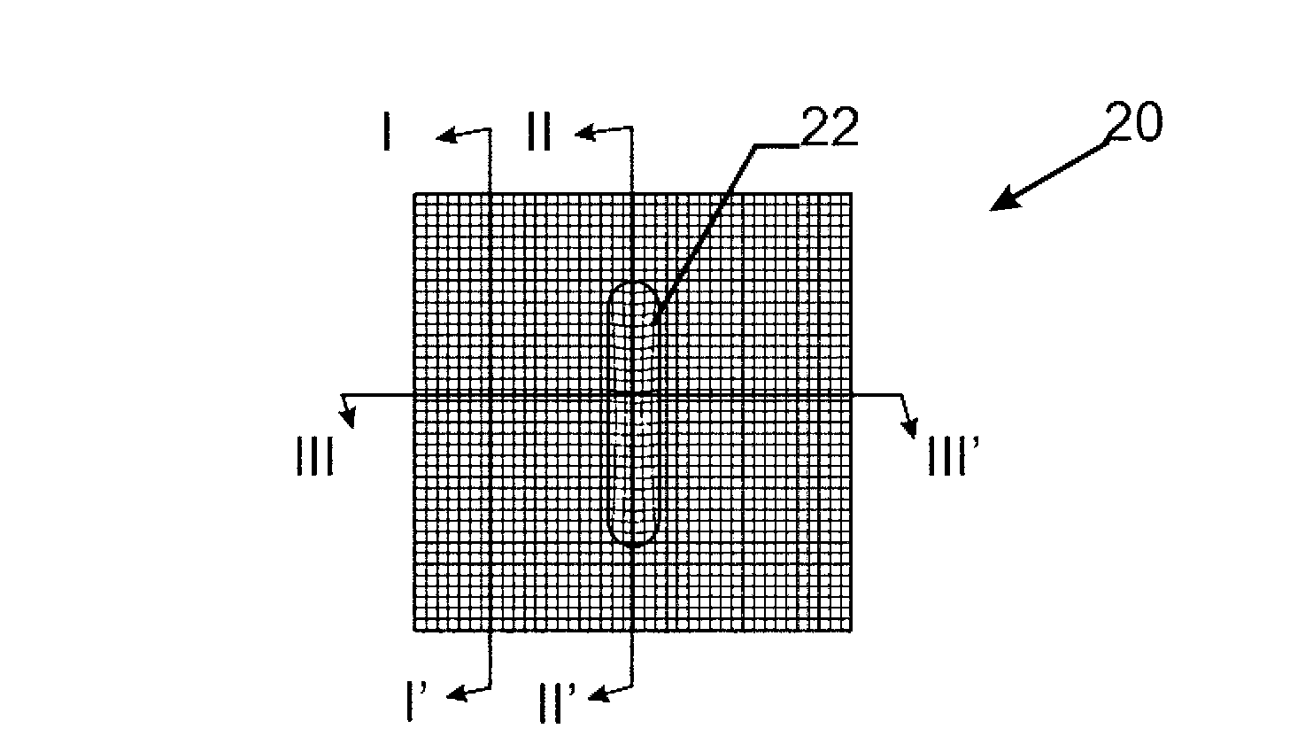
[0050] figure 2 A top view of a radiant screen 20 with protrusions 22 according to the invention is shown.

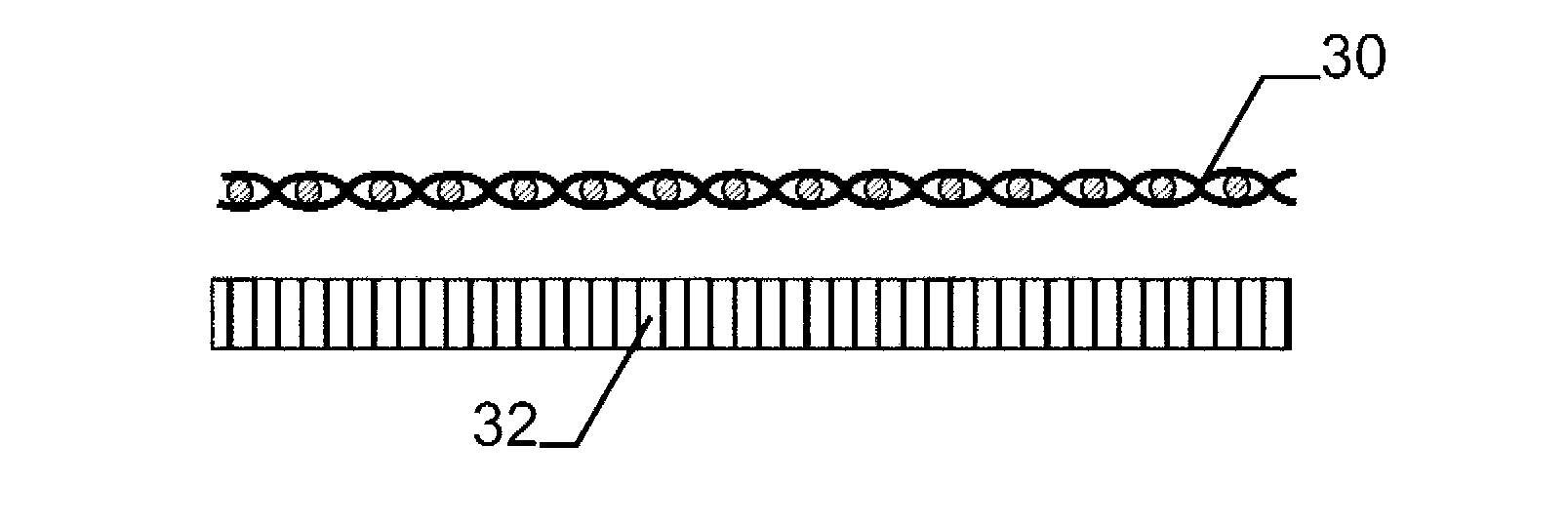
[0051] image 3 shown figure 2 Cross section at line I-I'. In this cross-section, the radiant screen 30 is straight and separated from the burner plate 32 by a certain distance.

[0052] Figure 4 shown figure 2 Cross-section at line II-II'. In this cross section, the radiant screen 40 is made to form a bulge at which the distance from the burner plate 42 is small.

[0053] Figure 5 shown figure 2 Cross section at line III-III'. In this cross section, the radiant screen 50 is made to form a bulge where the distance from the burner plate 52 is small.

[0054] Figure 6 An alternative embodiment of a gas-fired infrared radiation...


PUM


Abstract

The present invention relates to a gas fired infrared radiation emitter comprising a burner plate (140) acting as combustion surface and a radiant screen (160) positioned at the combustion side of the perforated tiles. The radiant screen is embossed (180) proving locally different distances between th burner plate and the radiant screen. The result is a higher performance of the gas fired infrared radiation emitter.

Description

technical field [0001] The invention relates to the technical field of gas-fired radiation emitters, which have a combustion surface and a radiation screen (or radiation screen) in front of the combustion surface. Background technique [0002] Gas-fired infrared radiation emitters are widely used in the pulp and paper industry to dry coatings on moving webs. Such emitters are well known; thus, one such emitter is described, for example, in US Patent No. 5,820,361. [0003] Prior art gas-fired infrared radiation emitters typically include a radiating (reflective, radiating) screen (or "grid") that increases the radiant power output of the emitter while preventing contamination of the primary radiating surface. An example of a launcher with a removable grill is disclosed in US Patent No. 5,820,361. [0004] Radiant burners comprising radiant burner plates and screens are also known from eg US4799879 or EP0539278. [0005] It is known in the art to use reinforced cross ribs ...

Claims


Application Information

Patent Timeline
Patent Type & Authority Applications(China)
IPC IPC(8): F23D14/14F23D14/16
CPCF23D14/16F23D2203/103F23D2203/105F23D14/147F23D14/149F23D14/145
Inventor P·勒努瓦V·欧拉尔德N·埃旺
Owner SOLARONICS
Learn More