Eureka AIR delivers breakthrough ideas for toughest innovation challenges, trusted by R&D personnel around the world.

Bearing arrangement for drive unit and adjustment drive with bearing arrangement

A technology of bearing device and drive unit, which is applied in the direction of rotating bearing, sliding contact bearing, rigid support of bearing components, etc., can solve problems such as consumption

Active Publication Date: 2016-11-16
ROBERT BOSCH GMBH
View PDF13 Cites 0 Cited by
  • Summary
  • Abstract
  • Description
  • Claims
  • Application Information

AI Technical Summary

Problems solved by technology

However, such a construction solution consisting of separate bearings and intermediate elements is relatively complex

Method used


Image

  • Bearing arrangement for drive unit and adjustment drive with bearing arrangement
  • Bearing arrangement for drive unit and adjustment drive with bearing arrangement
  • Bearing arrangement for drive unit and adjustment drive with bearing arrangement

Examples


Embodiment Construction

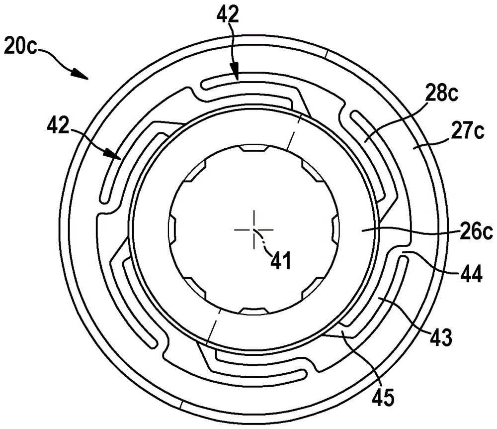
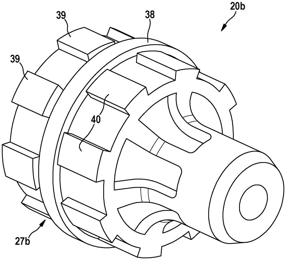
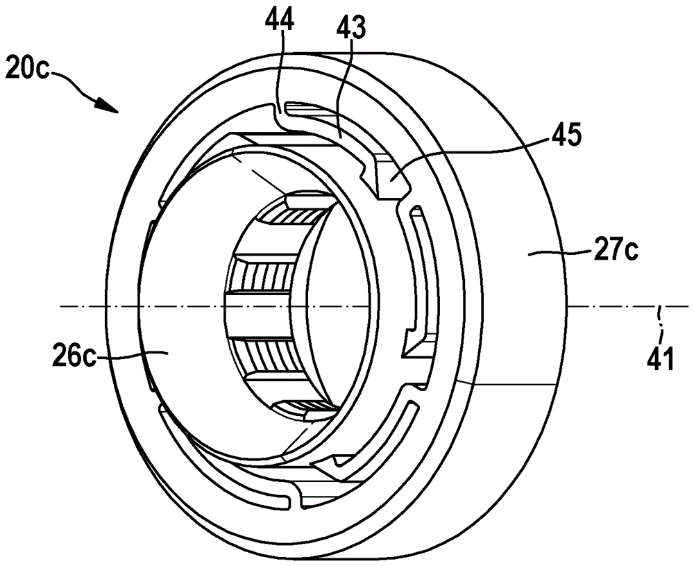
[0025] exist figure 1 A bearing arrangement 10 for a drive unit 1 is shown in a greatly simplified manner. The drive unit 1 is preferably used to operate an adjustment drive, in particular a comfort drive, such as a window lift drive or a seat adjustment drive in a motor vehicle, but either a front wiper drive or a rear wiper drive, but or an other transmission motor.

[0026] The drive unit 1 has, in particular, a drive motor 11 designed as an electric motor, which is driven via a drive shaft 12 in the figure 1 Drive via a component that is designed as a separate drive pinion 13 or as an integrated component of the drive shaft 12 . For this purpose, the drive pinion 13 is in particular press-fitted into the drive shaft 12 and has an external toothing 14 on its outer circumference. The external toothing 14 or the drive pinion 13 is arranged in operative connection with a transmission element designed as a driven element, in particular a worm wheel 15 , which has an outer ci...


PUM


Abstract

The invention relates to a bearing device (10) for a drive unit (1), wherein the drive unit (1) has a drive motor (11) which interacts with a transmission element (15) via a drive shaft (12) with multiple bearings, having a first bearing (18) which is arranged on the opposite side of the drive motor (11) with respect to the transmission element (15), a second bearing (19) which is arranged between the drive motor (11) and the transmission element (15), and a third bearing (20; 20a; 20b; 20c) which is arranged on the side of the transmission element (15) which faces away from the drive motor (11), wherein the third bearing (20; 20a; 20b; 20c) is arranged so as to be movable in a direction perpendicular to the longitudinal axis of the drive shaft (12). According to the invention there is provision that the third bearing (20; 20a; 20b; 20c) is embodied as a single-piece component which both accommodates the drive shaft (12) at its end region (30) and is accommodated in a receptacle (24) of a positionally fixed element, in particular a housing element.

Description

Background technique [0001] The invention relates to a bearing arrangement for a drive unit according to the preamble of claim 1 . Furthermore, the invention relates to an adjusting drive having a bearing arrangement according to the invention. [0002] In the case of bearing arrangements of this type known from practice for drive units, the drive shaft of the electric motor is connected via a drive pinion to a worm gear which is part of a transmission. The worm gear is also used, for example, to bring about an adjustment of a window regulator or a seat in a motor vehicle. Especially in the case of relatively small diameters of the drive shaft (generally a diameter of less than about 6 mm here), the external toothing of the drive pinion and The radial offset of the contact points between the teeth of the worm wheel has a negative effect not only on noise but also on wear. For this reason, it is already known in the prior art to install an additional third bearing for the dr...

Claims


Application Information

Patent Timeline
Patent Type & Authority Patents(China)
IPC IPC(8): F16C17/02F16C27/02F16C27/06F16C33/20H02K7/08
CPCF16C33/20F16C17/02F16C27/063F16C2208/10F16C2380/27H02K7/081
Inventor T.米利S.鲍尔M.赫斯格斯D.劳克
Owner ROBERT BOSCH GMBH
Why Eureka
Eureka Blog
Learn More