Phased-array antenna subarray for circularly polarized wide-angle scanning

A phased array antenna, wide-angle scanning technology, applied in the direction of antenna array, antenna, antenna grounding switch structure connection, etc., can solve the problems of low detectability of aircraft radar, large scanning blind area of ​​phased array antenna, and deterioration of axial ratio. , to achieve the effect of low radar and low detectability, large angle gain improvement, and reduction of difficulty and cost

Inactive Publication Date: 2013-08-14
10TH RES INST OF CETC
View PDF5 Cites 17 Cited by
  • Summary
  • Abstract
  • Description
  • Claims
  • Application Information

AI Technical Summary

Problems solved by technology

The traditional mechanical scanning array antenna with a fixed beam has a complex structure, heavy weight, and requires a servo system, which makes the scanning speed too slow, which is not in line with the design ideas of today's aircraft.
[0004] The prior art uses circularly polarized units as phased array antenna array units, and the array arrangement often adopts some regular forms, such as matrix arrangement. In the scanning area of ​​the angle, the gain reduction and axial ratio deterioration of the phased array antenna are very serious
In addition, at this time, the phased array antenna will also have serious anti-rotation problems.
[0005] In the prior art, in order to implement the protection of the antenna, the radome, which is unfavorable to the aerodynamic characteristics of the aircraft and the low detectability of the radar, is installed at the installation position of the airborne antenna

Method used


Image

  • Phased-array antenna subarray for circularly polarized wide-angle scanning
  • Phased-array antenna subarray for circularly polarized wide-angle scanning

Examples


Embodiment Construction

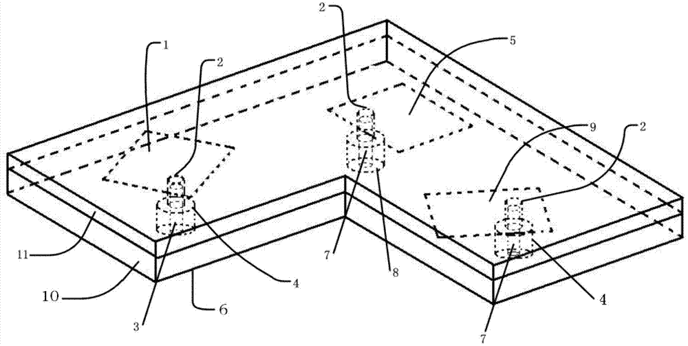
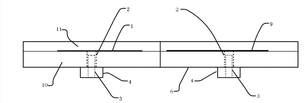
[0015] refer to figure 1 , figure 2 . In a best implementation example described below, the wide-angle scanning circularly polarized phased array antenna sub-array mainly includes: laminated on the microstrip antenna dielectric board 10, using one or more layers of materials with wave-transmitting properties to The fabricated covering protection layer 11 and three circularly polarized microstrip antenna units replace the radome. This protective layer can be a whole board covering the complete antenna array constructed by sub-arrays. The metal layer 6 under the microstrip antenna dielectric board 10 is the metal ground of the three microstrip antenna units. Three metallized via holes 2 run through the microstrip antenna dielectric board 10 and the radiation patch on the microstrip antenna unit. The diameter of the coaxial joint inner core 3 is smaller than the diameter of the metallized via hole 2, and there is a certain gap between them . The radiation patch can be in th...


PUM


Abstract

The invention provides a phased-array antenna subarray for circularly polarized wide-angle scanning, and aims at providing a phased-array antenna subarray which has a good wide-angle scanning gain characteristic and a good wide-angle scanning circular polarization characteristic, and can avoid derotation properly. The phased-array antenna subarray is achieved by the technical scheme as follows: three circularly polarized microstrip antenna radiation patches are distributed on a microstrip antenna dielectric plate (10) in a ternary rotary inversion subarray form; a metal layer (6) at the lower part of the microstrip antenna dielectric plate serves as a metal place for three microstrip antenna units; each coaxial joint inner core (3) and each coaxial joint outer core (4) form a coaxial feeding port; each coaxial outer core is connected with the metal place; each coaxial joint inner core is connected with the corresponding radiation patch located in the microstrip antenna dielectric plate in blind-inserting and non-contact manners; and the coaxial feeding ports perform electromagnetic coupling feeding and implement phase compensation on the microstrip antenna units to obtain a subarray radiating left-hand circular polarization electromagnetic waves or a subarray radiating right-hand circular polarization electromagnetic waves.

Description

technical field [0001] The invention relates to a phased array antenna sub-array suitable for circular polarization wide-angle scanning by a phased array antenna. Background technique [0002] Nowadays, airborne array antennas have gradually transitioned from the earliest fixed-beam mechanical scanning array antennas to phased array antennas, and phased array antennas are divided into passive phased array antennas and active phased array antennas. The requirements of modern advanced combat aircraft platforms for airborne antennas mainly include: try to be consistent with the shape of the fuselage, and appear in the form of a low profile, so as not to destroy the original aerodynamic characteristics of the combat aircraft and obtain better radar low detectability; Reduce weight and reduce the burden of combat aircraft take-off weight. [0003] At the same time, in some applications of airborne antennas, phased array antennas are required to perform circularly polarized wide-...

Claims


Application Information

Patent Timeline
IPC IPC(8): H01Q1/28H01Q1/40H01Q1/50H01Q21/00
Inventor 张剑任思蓝海张云何海丹
Owner 10TH RES INST OF CETC
Why Eureka
Try Eureka