
Battery terminal with current sensor

A current sensor and battery terminal technology, which is applied to small-sized batteries/battery packs, battery pack parts, battery boxes/coats, etc., can solve the problems of rapid battery consumption, prevent appearance deterioration, have sufficient strength, and eliminate influence Effect

Inactive Publication Date: 2013-07-24
YAZAKI CORP
View PDF8 Cites 9 Cited by
  • Summary
  • Abstract
  • Description
  • Claims
  • Application Information

AI Technical Summary

Problems solved by technology

The increase in electrical components is known to lead to a sharper drain on the battery in the car

Method used


Image

  • Battery terminal with current sensor
  • Battery terminal with current sensor
  • Battery terminal with current sensor

Examples


no. 1 example

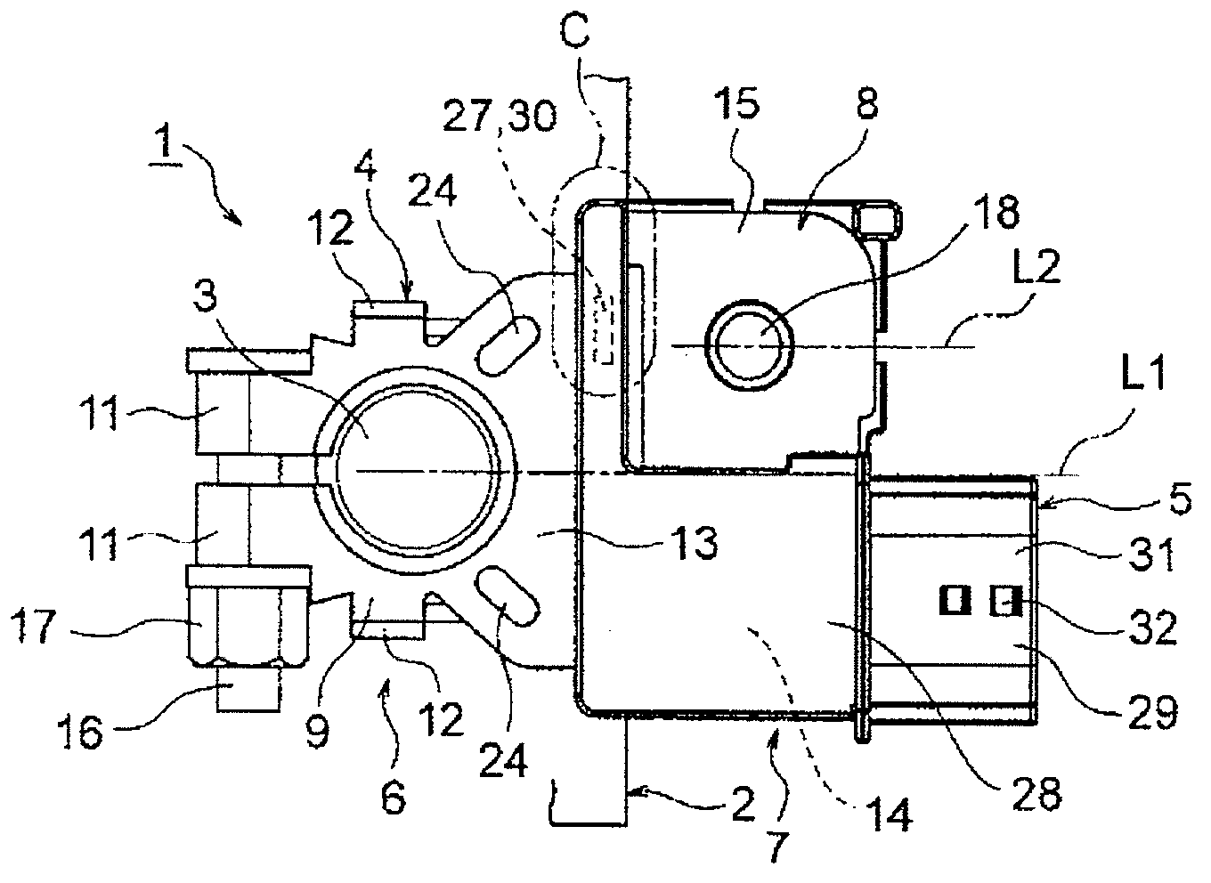
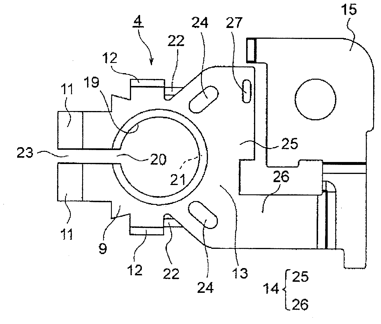
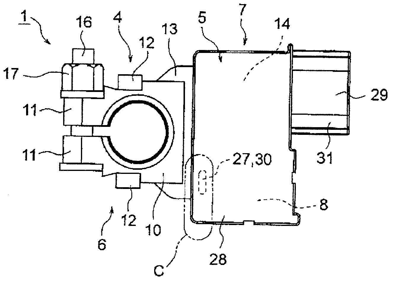
[0049] Hereinafter, a first embodiment will be described with reference to the drawings. Figure 1A to Figure 4B are a plan view, a bottom view, and a perspective view of a battery terminal with a current sensor and a battery terminal portion constituting the battery terminal with a current sensor according to a first embodiment of the present invention. Figure 7 is a plan view of another battery terminal portion according to another illustrative embodiment.

[0050] FIG. 1 shows a battery terminal 1 with a current sensor. A battery terminal 1 with a current sensor has: a battery terminal portion 4 connected to a battery post 3 of a battery 2 to be mounted on a mobile body such as an automobile; and a current sensor 5 passed through a resin The molding is integrated with the battery terminal part 4, but the configuration of the battery terminal 1 with a current sensor is not limited thereto.

[0051] The battery terminal 1 with current sensor has such a structure that the p...

no. 2 example

[0083] Hereinafter, a second embodiment will be described with reference to the drawings. Figure 5 is a perspective view of a battery terminal with a current sensor according to a second embodiment of the present invention. in addition, Figure 6A yes Figure 5 A plan view of the battery terminals with current sensors, and Figure 6B yes Figure 5 The plan view of the battery terminal part.

[0084] Figure 5 , Figure 6A with Figure 6B A battery terminal 41 with a current sensor according to a second embodiment is shown. The battery terminal with current sensor 41 has a battery terminal portion 42 connected to the battery post 3 of the battery 2 (see FIG. 1 ), and a current sensor 43 integrated with the battery terminal portion 42 by resin molding.

[0085] The battery terminal part 41 with a current sensor has: the pole part 44 of the battery terminal part 42, and the pole part 44 is a part connected to the battery pole 3 (see FIG. 1); the sensor part 45, the sensor pa...


PUM


Abstract

There is provided a battery terminal with current sensor capable of preventing an integrated part by a resin molding from being separated. A battery terminal with current sensor includes: a battery terminal part (4) that is formed by a conductive metal plate, and that includes a post part (6) to be connected to a battery post of a battery; a current sensor (5) that is integrated with the battery terminal part (4) by a resin molding, and that includes a stud part (8) to be connected to a load; and a sensor part (7) that corresponds to an integrated part of the battery terminal part (4) and the current sensor (5). The sensor part (7) includes a penetration portion (27) having a hole or slit shape that is formed at a part to be resin-molded of the battery terminal part (4), and a filling portion (30) that is formed at a resin-molded part of the current sensor (5) and fills the penetration portion (27).

Description

technical field [0001] The present invention relates to a battery terminal provided with a current sensor by assembling the current sensor in a battery terminal portion. Background technique [0002] In recent years, as automobiles have become highly functional, electrical components have also increased in number. It is known that the increase in electrical components leads to a sharper drain on the battery in the car. The battery terminal is connected to the battery post of the battery. The battery terminal is connected to the end terminal of the cable terminal. A current sensor for monitoring the remaining capacity of the battery is assembled to the end terminal. This current sensor has a substantially annular core and a Hall element, and is inserted and assembled to an end terminal (for example, see Patent Document 1). [0003] reference list [0004] patent documents [0005] Patent Document 1: Japanese Patent Document JP2002-141054A (Figure 4 and Figure 5 ) Con...

Claims


Application Information

Patent Timeline
Patent Type & Authority Applications(China)
IPC IPC(8): H01R11/28H01R13/66H01M50/552H01M50/562H01M50/569
CPCH01R13/405H01R13/6683G01R31/3696H01R11/287H01M2/30G01R31/364Y02E60/10H01M50/562H01M50/552H01M50/569B29L2031/3468B29L2031/3481B29L2031/36B29C45/14639H01R13/66H01R11/28
Inventor 植松聡
Owner YAZAKI CORP
Learn More