
Combined hydraulic drawbench jaw plate

A technology of machine pliers and jaw plates, which is applied to the field of jaw plates for hydraulic cold drawing machines, can solve the problems of low material utilization rate, high production cost, single jaw plate, etc., saving financial resources and manpower, saving replacement time, The effect of material reduction

Inactive Publication Date: 2013-07-24
宜兴市创天管业有限公司
View PDF5 Cites 11 Cited by
  • Summary
  • Abstract
  • Description
  • Claims
  • Application Information

AI Technical Summary

Problems solved by technology

[0002] The jaw plate of the existing technology is a single working part, once damaged, it must be replaced as a whole, the production cost is high, and the material utilization rate is low, the replacement is cumbersome, and needs to be improved

Method used


Image

  • Combined hydraulic drawbench jaw plate
  • Combined hydraulic drawbench jaw plate

Examples


Embodiment Construction

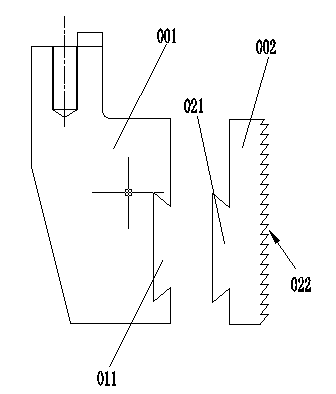
[0011] A combined hydraulic puller jaw plate, comprising a clamping part 001 and a jaw working part 002 snapped into the clamping part 001. The clamping part 001 is a square base body with a width of 140 mm, and one side wall of the base body There is a dovetail notch 011 penetrating transversely in the center, a dovetail protrusion 021 matching with the dovetail notch 011 is provided at one end of the jaw working part 002 , and a serrated 022 is provided on the other end surface. The jaw working part 002 is 45# steel after carburizing and quenching.


PUM

PropertyMeasurementUnit
widthaaaaaaaaaa
widthaaaaaaaaaa

Abstract

The invention relates to a combined hydraulic drawbench jaw plate, which comprises a clamping part and a jaw working part clamped and embedded in the clamping part. The clamping part is a square matrix. The sidewall center at one end of the matrix is provided with a horizontally perforating dovetail rabbet. One end of the jaw working part is provided with a dovetail shaped bulge matching the dovetail rabbet, and the surface of the other end is set in a jagged shape.

Description

technical field [0001] The invention relates to a jaw plate for a hydraulic cold drawing machine. Background technique [0002] The jaw plate of the prior art is a single working part, which must be replaced as a whole once it is damaged, the production cost is high, and the material utilization rate is low, the replacement is cumbersome, and needs to be improved. Contents of the invention [0003] Aiming at the above-mentioned shortcomings, the present invention provides a combined hydraulic puller jaw plate which is easy to replace and has a long service life. [0004] In order to solve the above technical problems, the present invention provides the following technical solutions: a jaw plate of a combined hydraulic puller, which is characterized in that it includes a clamping part and a jaw working part snapped on the clamping part, and the clamping part It is a square base body, with a dovetail notch transversely penetrating through the center of the side wall at one ...

Claims


Application Information

Patent Timeline
Patent Type & Authority Applications(China)
IPC IPC(8): B21C1/28
Inventor 殷世春任辉任小兵
Owner 宜兴市创天管业有限公司
Learn More