A method and device for sending an uplink signal
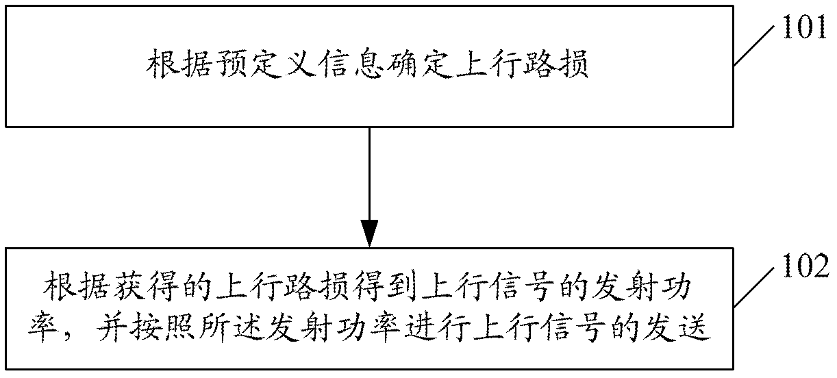
A signal transmission and signal technology, applied in the field of uplink signal transmission methods and devices, can solve problems such as user interference in adjacent cells, inaccurate estimation of signal transmission power, and influence on uplink signal reception.
- Summary
- Abstract
- Description
- Claims
- Application Information
AI Technical Summary
Problems solved by technology
Method used
Image
Examples
Embodiment 1
[0090] Here, the first embodiment is based on a coordinated multi-point system or a single-antenna or multi-antenna system that only introduces CSI-RS;
Embodiment 1-1
[0092] In Embodiment 1-1, the predefined information includes CSI-RS and signal type, and the uplink path loss determined according to the predefined information is: the path loss value measured from the same fixed CSI-RS port is used as PUCCH, PUSCH And the estimated value of the SRS uplink path loss; the fixed CSI-RS port can be any one of port 15 to port 22 or a fixed one, such as port 15.
[0093] For ease of description, Embodiment 1-1 only takes PUSCH as an example, and the calculation formula of its channel transmit power can be:
[0094]
[0095] Where parameter i represents subframe i; j is a high-level configuration parameter, with values 0, 1, 2; P CMAX, c (i) is the maximum allowable transmit power on this carrier; M PUSCH, c (i) The size of the PUSCH resource allocated on subframe i on this carrier, represented by RB; P O_PUSCH, c (j) Represents the UE's target transmit power when the channel transmission requirements are met without considering the influence of pa...
Embodiment 1-2
[0098] In Embodiment 1-2, the predefined information includes CSI-RS and signal type, and the uplink path loss determined according to the predefined information is: the path loss values measured from the same CSI-RS port are used as PUCCH, PUSCH and The estimated value of the SRS uplink path loss, where the CSI-RS port may be port 15 configured through higher layer signaling.
[0099] For ease of description, embodiment 1-2 only takes PUSCH as an example, and the calculation formula of its channel transmit power can be:
[0100]
[0101] Among them, parameter i represents subframe i; j is a high-level configuration parameter with values of 0, 1, 2; P CMAX, c (i) is the maximum allowable transmit power on this carrier; M PUSCH, c (i) is the size of the PUSCH resource allocated on subframe i on this carrier, represented by RB; P O_PUSCH, c (j) Represents the UE's target transmit power when the channel transmission requirements are met without considering the influence of path ...
PUM
 Abstract
Description
Claims
Application Information
 - Generate Ideas
- Intellectual Property
- Life Sciences
- Materials
- Tech Scout
- Unparalleled Data Quality
- Higher Quality Content
- 60% Fewer Hallucinations
Browse by: Latest US Patents, China's latest patents, Technical Efficacy Thesaurus, Application Domain, Technology Topic, Popular Technical Reports.
© 2025 PatSnap. All rights reserved.Legal|Privacy policy|Modern Slavery Act Transparency Statement|Sitemap|About US| Contact US: help@patsnap.com


