
Multi-stage heat pump compressor

A compressor, multi-stage technology, applied in the field of compressors, can solve the problems of the compressor being bulky, noisy, and the uneven force on the connecting shaft 30, and achieve the effect of good service life and operational stability.

Active Publication Date: 2015-10-07
FUSHENG IND CO LTD
View PDF7 Cites 0 Cited by
  • Summary
  • Abstract
  • Description
  • Claims
  • Application Information

AI Technical Summary

Problems solved by technology

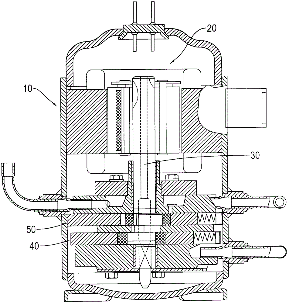
[0004] However, the above-mentioned conventional two-stage compressor has the following disadvantages, wherein, because the positions of the first compression member 40 and the second compression member 50 are all concentrated at one end of the connection shaft 30, the force on the connection shaft 30 is uneven, resulting in The connecting shaft 30 is unbalanced when it rotates, and noise is generated with the unbalanced rotation; in addition, when the refrigerant enters the second compression member 50 from the first compression member 40, an additional guide line is required, resulting in an increase in the volume of the compressor , resulting in bulky appearance of the compressor

Method used


Image

  • Multi-stage heat pump compressor
  • Multi-stage heat pump compressor
  • Multi-stage heat pump compressor

Examples


Embodiment Construction

[0052] The detailed description and technical content of the present invention will be described as follows with the accompanying drawings, but the attached drawings are only for illustration purposes and are not intended to limit the present invention.

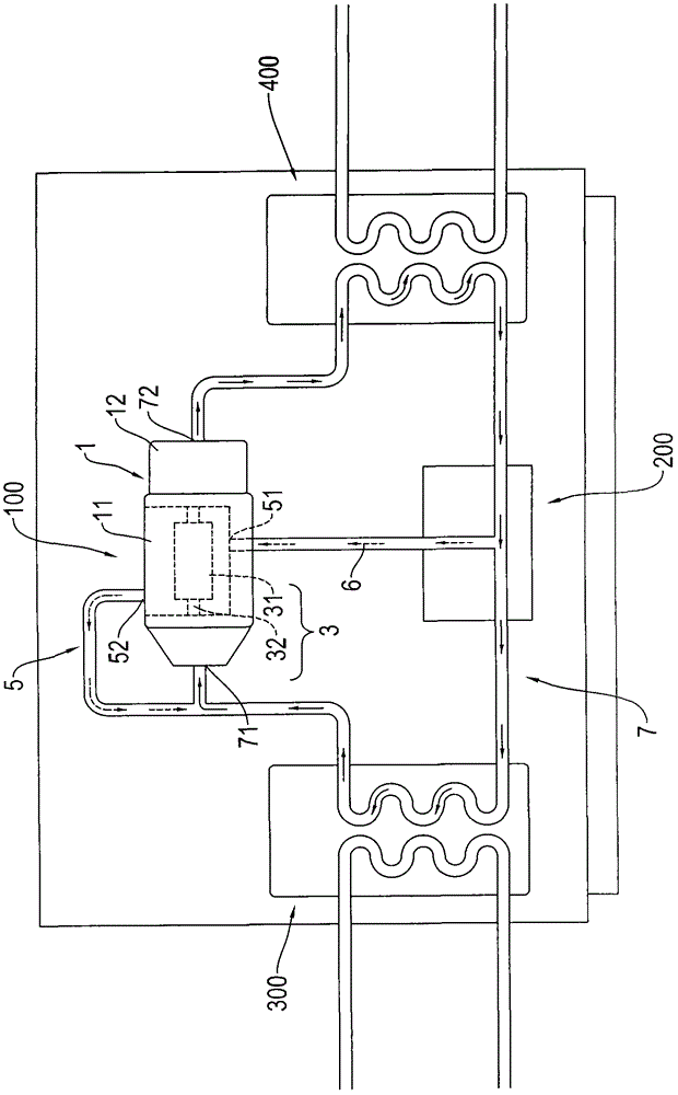
[0053] Please refer to figure 2 As shown, the present invention provides a multi-stage heat pump compressor. The multi-stage heat pump compressor 100 mainly includes a hermetic casing 1 , a partition assembly 2 , a driver 3 and at least two supercharging mechanisms 4 .

[0054] The partition assembly 2 is arranged in the airtight casing 1, and separates the airtight casing 1 into a first chamber 11 and a second chamber 12 which are isolated from each other, and the first chamber 11 is formed inside the second chamber 12; wherein The partition assembly 2 includes a partition 21 , two sealing elements 22 and a lubricant 23 , two sides of the partition 21 are respectively provided with a perforation 211 , and the lubricant 23 c...


PUM


Abstract

The invention discloses a multistage heat pump compressor. The multistage heat pump compressor comprises a closed shell, a separation assembly, a driver and at least two pressurizing mechanisms, the separation assembly is arranged in the closed shell and separates the closed shell into a first chamber and a second chamber which are mutually separated, and the first chamber is formed in the second chamber; the driver includes a body and a transmission shaft penetrating through the body, the body is accommodated in the first chamber, and the transmission shaft penetrates into the second chamber; and each of the pressurizing mechanisms is accommodated in the second chamber and is connected with the transmission shaft, and the pressurizing mechanisms are formed at two sides of the body to be driven by the driver to rotate. The bearing of the transmission shaft is uniform, so the rotation stability of the transmission shaft is improved and the noise is reduced, thereby the work efficiency of the compressor is enhanced.

Description

technical field [0001] The invention relates to a compressor, in particular to a multi-stage heat pump compressor. Background technique [0002] The heat pump compressor is a machine that must be used in heating machines or water heaters. It is mainly used to transport refrigerant through a specific process for heat exchange to reduce or increase the ambient temperature. The heat pump compressor is mainly composed of an evaporator, a compressor, an expansion valve, and a condenser. It transfers heat through natural heat exchange, and converts the useless heat in the natural environment into our daily usable energy through a thermal cycle and a small amount of electric energy. thermal energy. [0003] Among them, in order to increase the heat production efficiency of the compressor, a two-stage compressor is usually used to increase the gas pressure. Such as figure 1 As shown, it is a traditional two-stage compressor, which is mainly provided with an electric component 20 ...

Claims


Application Information

Patent Timeline
Patent Type & Authority Patents(China)
IPC IPC(8): F04C23/02F04C23/00F04D25/02F04D25/16
Inventor 洪明忠林维煦
Owner FUSHENG IND CO LTD
Learn More