Laser machining device

A laser processing and laser technology, which is applied in laser welding equipment, metal processing equipment, manufacturing tools, etc., can solve the problems of difficult control of laser beam modulation trajectory, unsuitable fine processing, and unsatisfactory problems, so as to improve the efficiency and quality of laser processing Effect

Active Publication Date: 2015-05-13
张立国
View PDF8 Cites 0 Cited by
  • Summary
  • Abstract
  • Description
  • Claims
  • Application Information

AI Technical Summary

Problems solved by technology

[0004] In the patent with the application number 200380110303.9, it is a better solution for the galvanometer to switch the laser focus. However, the circular modulation motion of the beam in front of the galvanometer is through the mirror, which reflects the modulated laser to make a circular motion. The disadvantage is that the laser is Do conical rotary motion, especially when two or more mirrors are used in combination, and the distance between the mirrors is slightly larger, the laser beam will be reflected many times, and the modulation trajectory of the laser beam is difficult to control, so it is not suitable for fine processing Happening
, this method is not ideal for high-speed and high-precision drilling with a small aperture below 100 microns, and the drilled hole type is an inverted cone with a small entrance and a large exit
[0005] The patent application number is 201210460145.0, the beam motion control before the galvanometer is relatively flexible, but because the flat optical element works in a swing mode, it is also difficult to obtain a very high-speed beam filling and scanning motion

Method used


Image

  • Laser machining device
  • Laser machining device

Examples


Embodiment 1

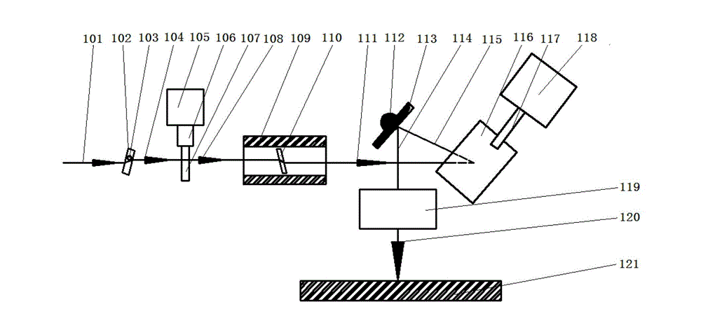
[0036] figure 1 Schematic diagram of the device structure for laser drilling of copper foil, such as figure 1 Shown: The copper foil laser drilling device includes an incident beam shifting motion control module, a laser beam rotating motion module, and a laser focusing and focus switching module.

[0037] The incident beam shifting motion control module includes two incident beam shifting units, namely a first incident beam shifting unit and a second incident beam shifting unit. The first incident beam shifting unit includes a first flat quartz glass 102 and a For the first motor driving the first flat quartz glass 102, the first flat quartz glass 102 is mounted on the motor spindle 103 of the first motor, and the motor spindle 103 of the first motor is axially perpendicular to the paper surface. The second incident beam shift unit includes a second flat quartz glass 107 and a second motor 105 for driving the second flat quartz glass 107, and the second flat quartz glass 107 is m...

Embodiment 2

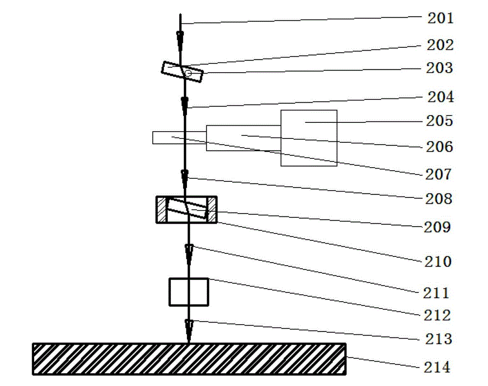
[0055] figure 2 A schematic diagram of the device structure for aluminum nitride ceramic laser milling blind grooves, such as figure 2 Shown: The device for aluminum nitride ceramic laser milling blind grooves includes an incident beam offset movement control module, a laser beam rotation movement module, and a laser focusing and focus switching module.

[0056] The incident beam shift motion control module includes two incident beam shift units, namely a first incident beam shift unit and a second incident beam shift unit. The first incident beam shift unit includes a first flat quartz glass 202 and a For driving the first motor (not shown in the figure) of the first flat quartz glass 202, the first flat quartz glass 202 is mounted on the motor shaft of the first motor, that is, on the first rotating shaft 203, the first The flat quartz glass 202 axially rotates around the first rotating shaft 203, and the axial direction of the first rotating shaft 203 is perpendicular to th...


PUM

PropertyMeasurementUnit
thicknessaaaaaaaaaa
thicknessaaaaaaaaaa
thicknessaaaaaaaaaa

Abstract

The invention relates to a laser machining device which comprises an incident beam deviation movement control module, a laser beam rotation movement module and a laser focusing and focus switching module. The transmission direction of an incident laser beam is modulated by the incident beam deviation movement control module to form a first beam transmitted to the laser beam rotation movement module, and the contour of the movement track of the first beam is automatically adjusted. A second beam outputted from the laser beam rotation movement module rotates along an optical axis of the first beam by the aid of the laser beam rotation movement module. The laser focusing and focus switching module is used for focusing the second beam outputted from the laser beam rotation movement module and controlling a laser focus to be switched over different machining units or controlling movement of the laser focus at one machining unit in an auxiliary manner. The laser machining device has the advantages that the contour of a rotating beam scan filling track can be automatically and dynamically changed, and machining speed and precision are high.

Description

Technical field [0001] The invention belongs to the field of laser processing, and in particular relates to a laser processing device for complex laser beam motion control. Background technique [0002] In the field of laser drilling, the laser focus is switched between the hole and the hole. At present, galvanometer scanning is the most mature and fastest switching method, which is manifested in high acceleration and deceleration, displacement linear velocity and positioning speed. The two-dimensional displacement platform is a very slow method and is generally rarely used. [0003] The patent application number 201010183539.7 uses the beam rotation module. The beam rotation diameter cannot be dynamically changed during the processing process. It is only suitable for use when the hole diameter of the same workpiece surface is less changed, so it has certain limitations. [0004] The patent application number 200380110303.9. The galvanometer is a better solution for switching the la...

Claims


Application Information

Patent Timeline
Patent Type & Authority Patents(China)
IPC IPC(8): B23K26/08B23K26/04B23K26/046
Inventor 张立国
Owner 张立国
Why Eureka
Try Eureka