
Steel wire micro-kinetic-friction abrasion testing machine

A fretting friction and wear test technology, applied in the direction of testing wear resistance, non-electric variable control, instruments, etc., can solve problems such as the inability to achieve stepless changes, the sliding stroke error of the fretting table, and the adjustment of pressure loads, and achieve structural Simple, high test accuracy, easy to operate

Inactive Publication Date: 2013-07-10
SHENZHEN INST OF SPECIAL EQUIP INSPECTION & TEST
View PDF5 Cites 14 Cited by
  • Summary
  • Abstract
  • Description
  • Claims
  • Application Information

AI Technical Summary

Problems solved by technology

However, when it is necessary to use the micro-motion table for friction and wear tests with different strokes, it is necessary to replace the cams of different shapes to change the amplitude of the micro-motion table
Since each cam can only correspond to a fixed sliding stroke, the cam driving method, even if the cam can be replaced, the adjustment of the sliding stroke of the micro-motion stage is also step-by-step, and it is impossible to achieve stepless change, which requires gradual adjustment of the sliding stroke The friction and wear test of the
At the same time, since the cam itself will be worn during use so that the shape will gradually change, the sliding stroke of the micro-motion table driven by the cam will also produce larger and larger errors.
Furthermore, the pressure weight is used to form contact pressure on the surface of the micro-motion table. Although the load is stable and the structure is simple, it is difficult to continuously and steplessly adjust the pressure load.

Method used


Image

  • Steel wire micro-kinetic-friction abrasion testing machine
  • Steel wire micro-kinetic-friction abrasion testing machine
  • Steel wire micro-kinetic-friction abrasion testing machine

Examples


Embodiment Construction

[0022] In order to make the object, technical solution and advantages of the present invention clearer, the present invention will be further described in detail below in conjunction with the accompanying drawings and embodiments. It should be understood that the specific embodiments described here are only used to explain the present invention, not to limit the present invention.

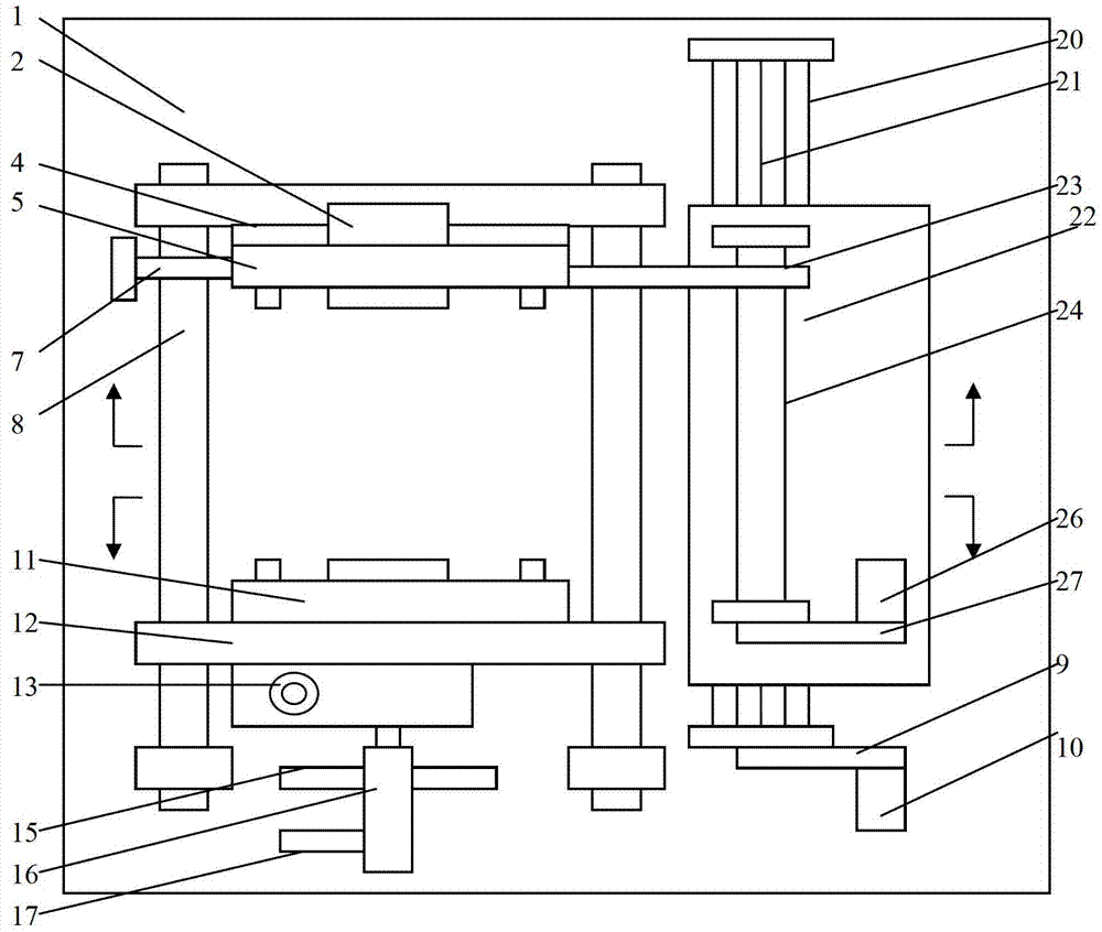
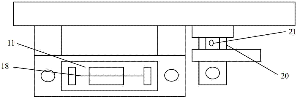
[0023] figure 1 The steel wire fretting friction and wear testing machine provided by the preferred embodiment of the present invention is shown. The testing machine includes a main frame 1 and an upper workbench 5 installed on the main Loading mechanisms 15, 16, 17, micro-motion displacement amplitude adjustment mechanisms 2, 20, 21, 22, 9, 10, micro-motion displacement frequency adjustment mechanisms 4, 7, 23, 24, 26, 27.

[0024] Please also refer to figure 2 and image 3 , the lower surface of the upper workbench 5 is fixedly equipped with an upper sample steel wire 28 of a predetermined ty...


PUM


Abstract

The invention discloses a steel wire micro-kinetic-friction abrasion testing machine which comprises a main rack, and an upper working platform and a lower working platform which are arranged on the main rack, wherein an upper sample steel wire is fixed on the upper working platform, a lower sample steel wire is fixed on the lower working platform, and the upper sample steel wire is in contact with the lower sample steel wire. The steel wire micro-kinetic friction abrasion testing machine also comprises a micro inching displacement frequency regulating mechanism and a micro inching displacement amplitude regulating mechanism, wherein the micro inching displacement frequency regulating mechanism is used for driving the upper working platform to reciprocate relative to the lower working platform so as to form friction between the upper sample steel wire and the lower sample steel wire for carrying out a steel wire friction abrasion test, the micro inching displacement frequency regulating mechanism is also steplessly regulating the reciprocating frequency of the upper working platform, and the micro inching displacement amplitude regulating mechanism is used for steplessly regulating the reciprocating amplitude of the upper working platform.

Description

technical field [0001] The invention relates to friction performance testing, in particular to a steel wire fretting friction and wear testing machine. Background technique [0002] The fretting friction and wear testing machine is a test device used to test and study the parameters related to friction such as hardness, friction performance and wear fatigue performance of materials. Its basic working principle is to drive two surfaces in contact with each other under a certain contact pressure. Slip relative to each other with set amplitude, frequency and contact angle to create friction between the two surfaces, then measure and analyze various friction-related parameters of the materials that make up the two surfaces. [0003] At present, the scheme widely used in the steel wire fretting wear testing machine is to use the cam drive method to generate sliding with predetermined amplitude and frequency between two contacting surfaces, and use the method of pressing weights t...

Claims


Application Information

Patent Timeline
IPC IPC(8): G01N3/56G05D3/00
Inventor 王保卫运向勇程红星尹建利韩文涛
Owner SHENZHEN INST OF SPECIAL EQUIP INSPECTION & TEST
Learn More