
A message transmission method and device

A technology for message transmission and equipment, which is applied in the field of message transmission and can solve the problems such as the failure to forward the message of host 1 normally and the inability to realize the process.

Active Publication Date: 2016-06-08
XINHUASAN INFORMATION TECH CO LTD
View PDF5 Cites 0 Cited by
  • Summary
  • Abstract
  • Description
  • Claims
  • Application Information

AI Technical Summary

Problems solved by technology

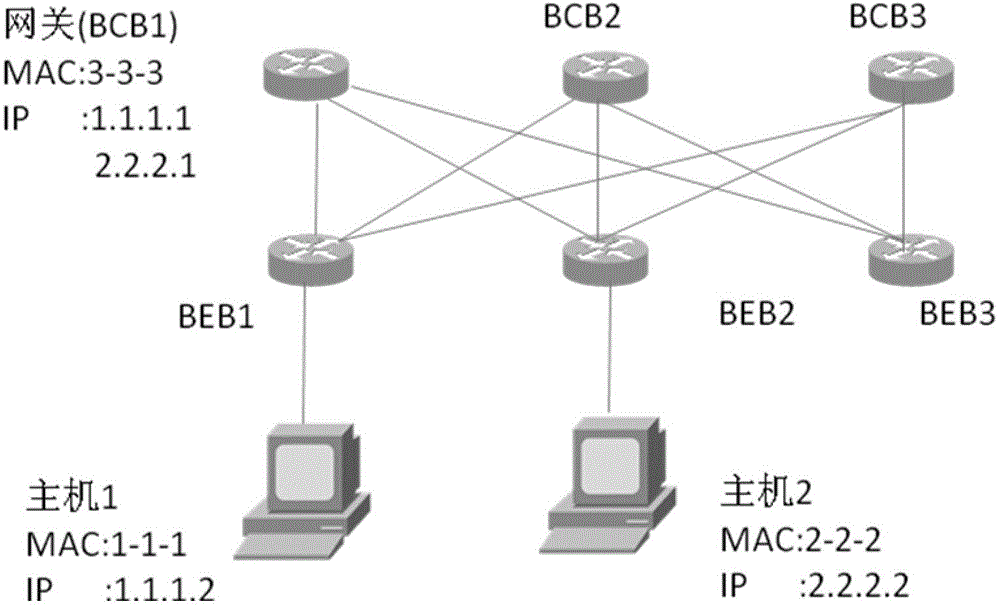
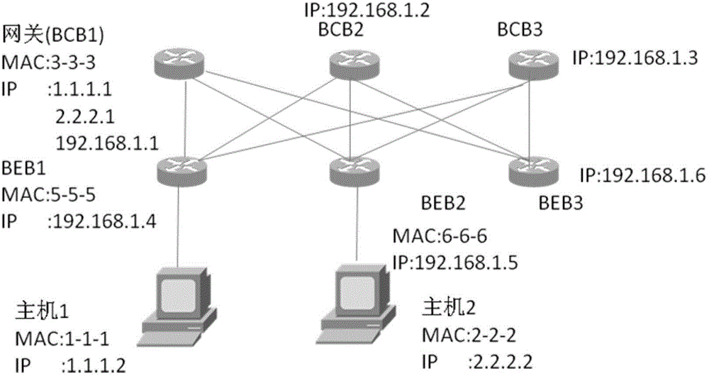
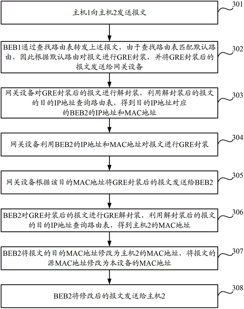
[0035] In the above steps 3 and 4, the gateway device needs to use the destination IP address to query the routing table first, and then use the destination MAC address to query the MAC address table; The process of querying the MAC address table by the destination MAC address makes the above process impossible, that is, the packet sent from host 1 to host 2 cannot be forwarded normally.

Method used


Image

  • A message transmission method and device
  • A message transmission method and device
  • A message transmission method and device

Examples


Embodiment Construction

[0092] The following will clearly and completely describe the technical solution of the present invention in conjunction with the accompanying drawings of the present invention. Obviously, the described embodiments are only some of the embodiments of the present invention, not all of them. Based on the embodiments of the present invention, all other embodiments obtained by persons of ordinary skill in the art without making creative efforts belong to the protection scope of the present invention.

[0093] Aiming at the problems existing in the prior art, the embodiment of the present invention proposes a message transmission method, which is applied to a large layer-2 network including a terminal device, an edge bridge device and a gateway device, wherein the edge bridge device and the terminal device direct connection, when the terminal device is the sending end device, the edge bridge device is the source end device, and when the terminal device is the receiving end device, t...


PUM


Abstract

The invention discloses a message transmission method and equipment. The method comprises: a gateway device receives a first message encapsulated by GRE from an edge bridge device, and decapsulates the first message to obtain a second message; the gateway device Find the local routing table according to the destination IP address of the second message; the gateway device performs GRE encapsulation on the second message according to the IP address and the MAC address of the edge bridge device corresponding to the found IP address of the second message Afterwards, a third packet is generated; the gateway device sends the GRE-encapsulated third packet to the corresponding edge bridge device. In the embodiment of the present invention, messages that need to be transmitted between different terminal devices can be forwarded normally.

Description

technical field [0001] The invention relates to the field of communication technology, in particular to a message transmission method and equipment in a large-scale two-layer network. Background technique [0002] STP (SpanningTreeProtocol, Spanning Tree Protocol) is used in the traditional three-tier data center architecture to optimize the path from the client to the server and support connection redundancy. Due to the convergence performance of STP, etc., the network size of STP generally does not exceed 100 switches. At the same time, because STP needs to block redundant devices and links, it also reduces the bandwidth utilization of network resources. Traditional STP-based backup equipment and link solutions can no longer meet the scale and bandwidth requirements of the data center, and the STP protocol's fault convergence time of several seconds to minutes cannot meet the reliability requirements of the data center. Therefore, it is necessary to have new technologies...

Claims


Application Information

Patent Timeline
Patent Type & Authority Patents(China)
IPC IPC(8): H04L12/741H04L12/46H04L29/12H04L45/74
Inventor 彭剑远郑国良
Owner XINHUASAN INFORMATION TECH CO LTD
Learn More