
Bus differential protection latching spare power automatic switching loop

A technology of bus differential protection and standby self-switching, which is applied to circuit devices, electrical components, emergency power supply arrangements, etc., and can solve problems such as reducing power supply reliability

Active Publication Date: 2013-06-19
STATE GRID CORP OF CHINA +2
View PDF3 Cites 9 Cited by
  • Summary
  • Abstract
  • Description
  • Claims
  • Application Information

AI Technical Summary

Problems solved by technology

[0009] To sum up, the blocking loop of the prior art can only play a good role in the bus distribution backup self-switching mode to ensure the reliability of power supply; while in the line backup self-switching mode, there is no need to block the backup self-switching mode, and even start To the opposite effect, reducing the reliability of power supply

Method used


Image

  • Bus differential protection latching spare power automatic switching loop
  • Bus differential protection latching spare power automatic switching loop
  • Bus differential protection latching spare power automatic switching loop

Examples


Embodiment Construction

[0024] In order to enable those skilled in the art to better understand the technical solutions in the present application, the technical solutions in the embodiments of the present application will be clearly and completely described below in conjunction with the drawings in the embodiments of the present application. Obviously, the described The embodiments are only some of the embodiments of the present application, but not all of them. Based on the embodiments in this application, all other embodiments obtained by persons of ordinary skill in the art without creative efforts shall fall within the scope of protection of this application.

[0025] The purpose of the present invention is to provide a bus differential protection locking standby self-switching circuit, which is applicable to the 110kV single bus section wiring mode of 110kV station, and improves the reliability of power supply of the power grid.

[0026] The 110kV site has two buses, bus I and bus II, and two l...


PUM


Abstract

An embodiment of the invention provides a bus differential protection latching spare power automatic switching loop. The loop is characterized in that a bus differential action contact I in a first group and a bus differential action contact II in a second group are parallelly connected and then connected into a latching mother stock spare power automatic switching loop to realize 'OR' logic latching mother stock spare power automatic switching, and another bus differential action contact I in the first group and another bus differential action contact II in the second group are serially connected and then connected into a spare power automatic switching main latching loop to realize 'AND' logic latching spare power automatic switching. Latching mother stock spare power automatic switching is ensured when any bus fails, spare power automatic switching success rate can be increased in a spare power automatic switching mode of a line, power supply reliability is improved, and failure of a device is avoided by latching spare power automatic switching when two buses simultaneously fail (possibly with dead zone failure or mother stock switch failure and the like).

Description

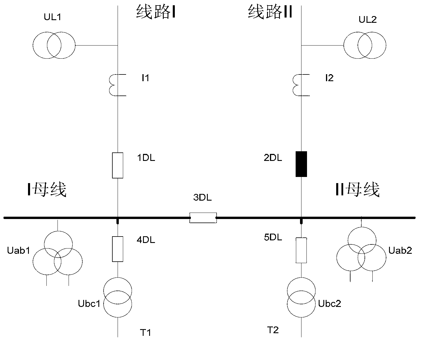
technical field [0001] The invention relates to the technical field of electric power system and automation thereof, in particular to a bus differential protection locking standby self-injection circuit. Background technique [0002] With the development of the national economy, the power grid has higher and higher requirements on the reliability of power supply. Bus differential protection and standby automatic switching are important system equipment to ensure the safe and stable operation of the power grid. In the power system, the 110kV busbars of some 110kV stations adopt single-busbar separate wiring, and are usually equipped with busbar differential protection and standby automatic switching. The main relationship of the circuit connection is ( figure 1 ): Connect two circuit breakers to Line I and Line II respectively. Wherein, the line I is the source power supply, and the line II is the backup power supply; or the line I is the backup power supply, and the line I...

Claims


Application Information

Patent Timeline
Patent Type & Authority Applications(China)
IPC IPC(8): H02J9/06
Inventor 郑建梓王斌陈东海王祎董艺
Owner STATE GRID CORP OF CHINA
Learn More