
A Method for Measuring Axial Strain Based on Birefringent Optical Fiber Environment

A birefringent optical fiber, axial strain technology, applied in measurement devices, optical devices, instruments, etc., can solve the problems of increasing cost and system complexity, and achieve the effect of convenient operation, satisfying sensitivity and high sensitivity

Active Publication Date: 2015-10-28
NANJING UNIV OF AERONAUTICS & ASTRONAUTICS
View PDF4 Cites 0 Cited by
  • Summary
  • Abstract
  • Description
  • Claims
  • Application Information

AI Technical Summary

Problems solved by technology

However, at present, more attention is paid to improving the sensing sensitivity of the birefringent fiber optic loop mirror through structural innovation, but the structural innovation method increases the cost and complexity of the system while improving the sensing sensitivity of the birefringent fiber optic loop mirror

Method used


Image

  • A Method for Measuring Axial Strain Based on Birefringent Optical Fiber Environment
  • A Method for Measuring Axial Strain Based on Birefringent Optical Fiber Environment
  • A Method for Measuring Axial Strain Based on Birefringent Optical Fiber Environment

Examples


Embodiment Construction

[0025] The specific implementation manners of the present invention will be further described in detail below in conjunction with the accompanying drawings.

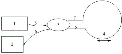
[0026] Such as figure 1 As shown, the present invention proposes a method for measuring axial strain based on a birefringent fiber environment, comprising the following steps:

[0027] Step 1. Use a fiber coupler, a birefringent fiber, a light source and a spectrometer to construct a birefringent fiber environment axial strain measurement device, wherein the two ends of the birefringent fiber are connected to the two output arms of the fiber coupler, and the light source is connected to the fiber The input arm of the coupler is connected, and the input end of the spectrometer is connected with the other output arm of the fiber coupler;

[0028] Step 2. Paste the birefringent optical fiber on the object to be measured, and measure its interference spectrum through a spectrometer;

[0029] Step 3. When the measured objec...


PUM


Abstract

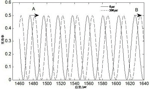
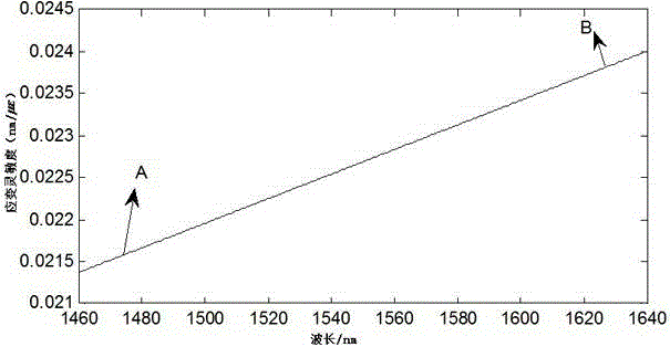
The invention relates to an axial strain measurement method based on a birefringent fiber environment. On the basis of constructing the existing axial strain measurement device for the birefringent fiber environment, axial strain is measured by choosing an optimal monitoring point. Not only can the smooth measurement of the strain be ensured, but also the strain flexibility is improved. Compared with a structural innovation method for improving the strain flexibility, the axial strain measurement method based on the birefringent fiber environment is simple and easy.

Description

technical field [0001] The invention relates to an axial strain measurement method based on a birefringence fiber environment. Background technique [0002] The application of birefringent fiber optic loop mirrors in the fields of optical communication and fiber optic sensing has attracted widespread attention from scholars. Birefringent fiber optic loop mirrors have polarization-independent, high extinction ratio, anti-interference from external loop mirrors, simple manufacturing, stable performance, and low price. Excellent characteristics. [0003] The birefringent fiber optic ring mirror axial strain measurement system consists of a fiber coupler, a birefringent fiber, a light source and a spectrometer. The two ends of the birefringent fiber are respectively welded to the two output arms of the fiber coupler to form a birefringent fiber ring mirror. The light source Input through the input arm of the fiber coupler, it is divided into a clockwise transmitted beam and a c...

Claims


Application Information

Patent Timeline
Patent Type & Authority Patents(China)
IPC IPC(8): G01B11/16
Inventor 曾捷江莺张倩韵周雅斌梁大开
Owner NANJING UNIV OF AERONAUTICS & ASTRONAUTICS
Learn More