Driving test system based on global position system (GPS)

A driving test and GPS positioning technology, applied in the GPS field, can solve the problems of unfavorable GPS technology promotion, inability to deduce the coordinate position of the test vehicle, and short service life

Inactive Publication Date: 2013-06-05
王恩惠
View PDF6 Cites 8 Cited by
  • Summary
  • Abstract
  • Description
  • Claims
  • Application Information

AI Technical Summary

Problems solved by technology

[0007] In the process of realizing the present invention, the inventor found that the direct contact detection method has problems such as large early construction, high failure rate, high maintenance cost and short service life in the future, and this type of method cannot be applied to actual road tests
Although the non-contact detection method has the advantages of low maintenance cost and long service life in the future, the detection accuracy of this method depends on the construction accuracy and debugging accuracy to a large extent, resulting in a large amount of construction and debugging work.
In addition, the non-contact detection method cannot be applied to the actual road test
Existing GPS detection method can only locate the position of the GPS receiving antenna installed on the test car, therefore, in some cases (as the vehicle travels very slowly, turns especially when parking), it is impossible to determine the direction of the test car , so it is impossible to infer the coordinates of other parts of the test vehicle, which is not conducive to the promotion of GPS technology in driving test applications

Method used


Image

  • Driving test system based on global position system (GPS)
  • Driving test system based on global position system (GPS)
  • Driving test system based on global position system (GPS)

Examples


Embodiment Construction

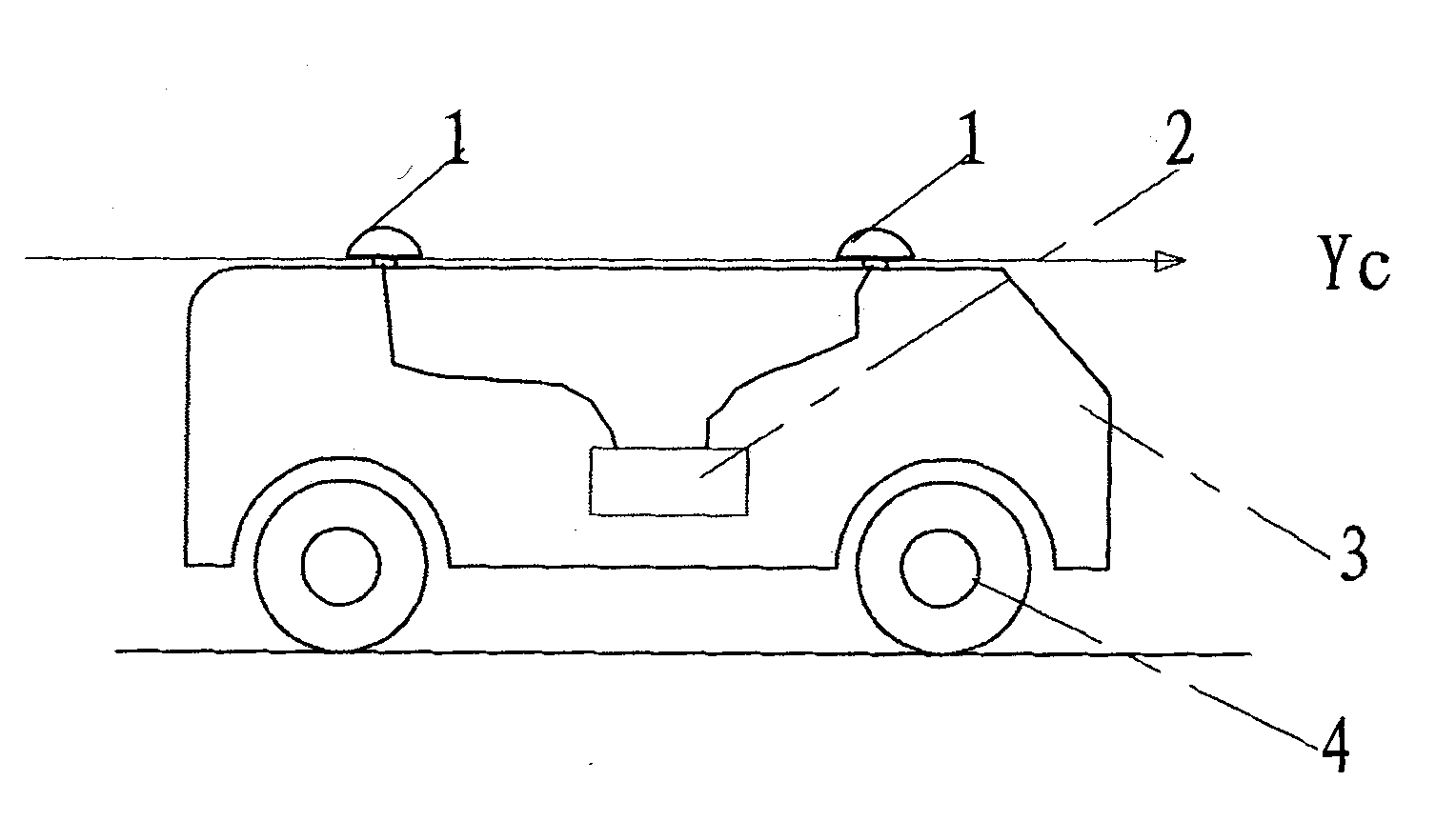
[0026] For further elaborating the technical means and effect that the present invention takes for reaching the intended invention purpose, below in conjunction with accompanying drawing and preferred embodiment, to the driving test system based on GPS proposed according to the present invention its specific implementation, structure, feature and effect Its effect is described in detail below.

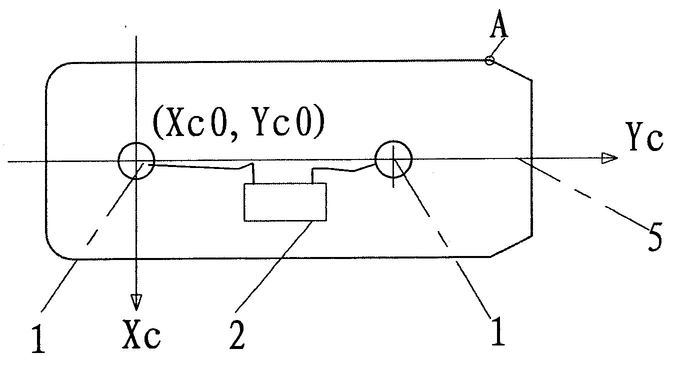
[0027] The GPS-based driving test system provided by the present invention mainly includes: a GPS positioning system and a main control device. The GPS positioning system is installed on the test vehicle, and the main control device can be installed on the test vehicle or in a fixed facility, such as in the monitoring room of the test room. When the main control device is installed in a fixed facility, One master control device can correspond to multiple GPS positioning systems.

[0028] The GPS positioning system and the main control device can be connected by wire, such as through a...


PUM


Abstract

The invention relates to a driving test system based on a global position system (GPS). The driving test system comprises a GPS positioning system and a master control device. The GPS positioning system comprises two GPS receiving antennas and a GPS positioning signal processor, wherein the two GPS receiving antennas are arranged on a test car and receive and output GPS positioning signals. The GPS positioning signal processor receives GPS positioning signals output by the two GPS receiving antennas and determines the coordinate positions of the two GPS receiving antennas according to the GPS positioning signals. The marker coordinate position in the test item is pre-stored in the master control device; and the master control device calculates the coordinate position of a preset portion of the test car in a preset coordinate system according to the coordinate positions of the two GPS receiving antennas, and determines the position relation of a marker and the preset portion of the test car in the preset coordinate system according to the marker coordinate position and the coordinate position of the preset portion of the test car. The driving test system reduces achievement cost and improves applicability of an electronic test system.

Description

technical field [0001] The invention relates to GPS technology, in particular to a driving test system based on GPS. Background technique [0002] In the initial driving test, the examiner follows the car to assess the driving level of the candidates. The traditional examination method tends to be replaced by the electronic examination system due to its shortcomings such as consuming police force, being easily affected by the subjective judgment of the examiner, and easily causing mental stress to the examinee. The electronic test systems that have been launched so far include: electronic pile test system, field electronic road test system and actual road electronic test system. [0003] There are mainly three ways to implement the driving test using the electronic test system: [0004] Implementation mode 1. Direct contact detection method. Install electronic devices (such as pressure sensors, infrared sensors, vibration sensors, piezoelectric hoses, etc.) on the test ve...

Claims


Application Information

Patent Timeline
IPC IPC(8): G09B19/16G01S19/51
Inventor 王恩惠
Owner 王恩惠
Why Eureka
Try Eureka