Machine room equipment radiating device for directly radiating to outside of machine room

A technology for cooling devices and computer rooms, which is applied in lighting and heating equipment, household heating, heating methods, etc. The effect of reducing dust and reducing power consumption of air conditioners

Inactive Publication Date: 2013-06-05
秦卫民
View PDF6 Cites 0 Cited by
  • Summary
  • Abstract
  • Description
  • Claims
  • Application Information

AI Technical Summary

Problems solved by technology

The disadvantages of the former are low efficiency and high power consumption, while the disadvantages of the latter are many problems caused by dust and moisture.

Method used


Image

  • Machine room equipment radiating device for directly radiating to outside of machine room
  • Machine room equipment radiating device for directly radiating to outside of machine room
  • Machine room equipment radiating device for directly radiating to outside of machine room

Examples


Embodiment Construction

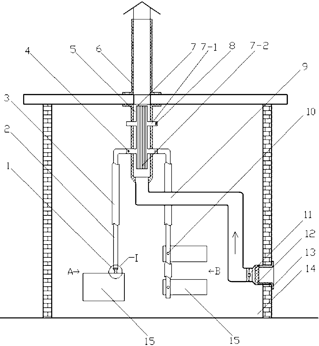
[0027] Depend on Figure 1-6 As can be seen from the shown embodiment, it includes a heat exhaust chimney 6, a heat collecting radiator 7 and a chamber 5 thereof, a heat conduction strip 2, a heat collection column 1, a temperature sensor 8, a temperature control fan 11 and an air duct 9 thereof and an anti- Dust net 12 and its support 13;

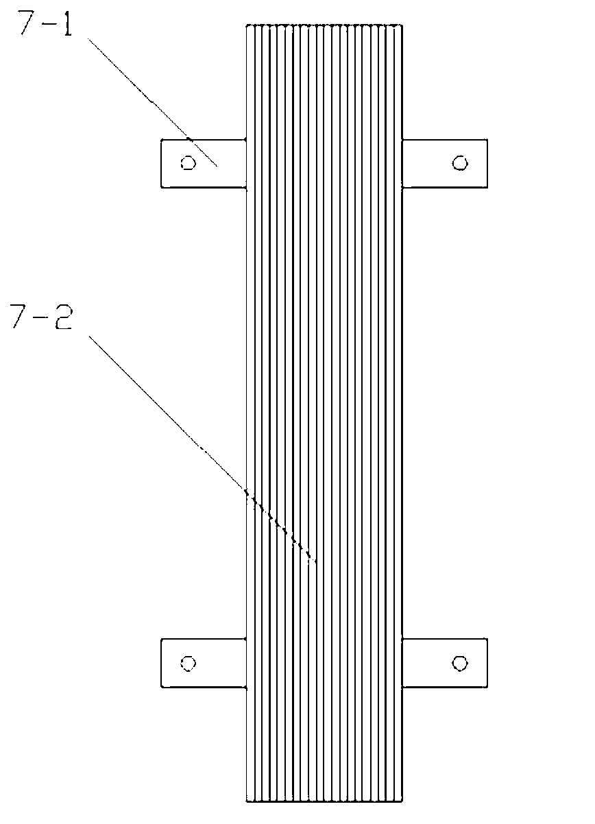
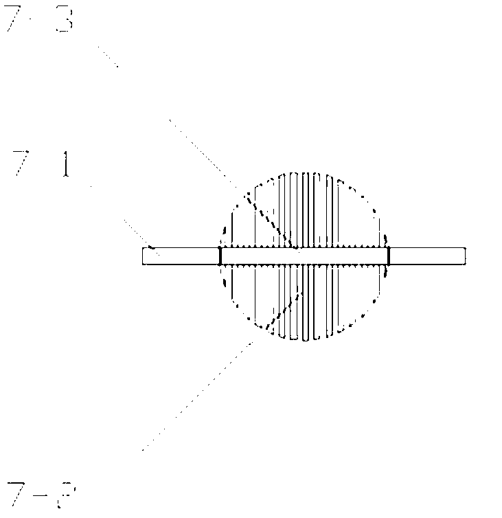
[0028] The heat collecting radiator 7 is made up of a heat collecting plate 7-3, a cooling fin 7-2 and more than 2 lugs 7-1 (the number of lugs depends on the quantity and distribution of equipment in the machine room, such as figure 1 Only two lugs are used, and other unused lugs are covered with heat-insulating sleeves); the heat collecting plate 7-3 is a rectangular plate made of heat-conducting material, and the cooling fins 7-2 are symmetrically distributed on the collecting On both sides of the heat plate 7-3, the lugs 7-1 are located on the two sides of the heat collecting plate 7-3 (see figure 2 and image 3 );

[0029] The he...


PUM


Abstract

The invention relates to a machine room equipment radiating device for directly radiating to the outside of a machine room. The radiating device comprises a heat discharging chimney, a heat collection radiator, a chamber of the heat collection radiator, heat conducting strip plates, heat collection columns, a temperature sensor, a temperature control fan, an air channel of the temperature control fan, a dust screen and a support of the dust screen. The heat collection radiator is composed of heat collection plates, radiating fins and more than two support lugs, the chamber of the heat collection radiator is fixed on a ceiling of the machine room through a flange, the heat discharging chimney is fixed on a roof of the machine room through a flange and communicated with the chamber of the heat collection radiator, an upper port of the air channel is communicated with a lower port of the chamber of the heat collection radiator, the temperature control fan is mounted on a port, communicated with the outside, of the air channel, the heat conducting strip plates are fixedly connected with radiating fins of heating devices of machine room equipment through the heat collection columns, and upper ends of the heat conducting strip plates are fixedly connected with the support lugs. The machine room equipment radiating device has the advantages that radiating efficiency can be improved, heat discharged by the equipment to the inside of the machine room is greatly reduced and completely eradicated, and power consumption of air conditioners is lowered greatly.

Description

technical field [0001] The invention relates to a cooling device for equipment in a computer room to directly dissipate heat to the outside of the computer room. Background technique [0002] The heat dissipation of the existing equipment in the computer room is mostly implemented through the air conditioner to implement "secondary energy conversion indirect heat removal", and a small amount of "primary energy conversion direct heat removal" is implemented through the fresh air system. The disadvantages of the former are low efficiency and high power consumption, while the disadvantages of the latter are many problems of dustproof and moisture-proof. Contents of the invention [0003] The technical problem to be solved by the present invention is to provide a cooling device for equipment in a computer room to directly dissipate heat to the outside of the computer room. [0004] The technical solution adopted by the present invention to solve its technical problems: ...

Claims


Application Information

Patent Timeline
Patent Type & Authority Applications(China)
IPC IPC(8): F24F5/00
Inventor 秦卫民秦齐
Owner 秦卫民
Why Eureka
Try Eureka