Indoor illumination control system

A technology for controlling systems and indoor lighting, applied in lighting installations, lighting and heating equipment, components of lighting installations, etc.

Inactive Publication Date: 2013-06-05
XIAN ELITE ELECTRONICS IND
View PDF0 Cites 2 Cited by
  • Summary
  • Abstract
  • Description
  • Claims
  • Application Information

AI Technical Summary

Problems solved by technology

[0003] In order to overcome the deficiencies of the above-mentioned prior art, the object of the present invention is to provide an indoor lighting control system, which solves the problem of automatic control of indoor lighting by using sunlight reflection method

Method used


Image

  • Indoor illumination control system
  • Indoor illumination control system

Examples


Embodiment Construction

[0008] The present invention will be described in further detail below in conjunction with the accompanying drawings and embodiments.

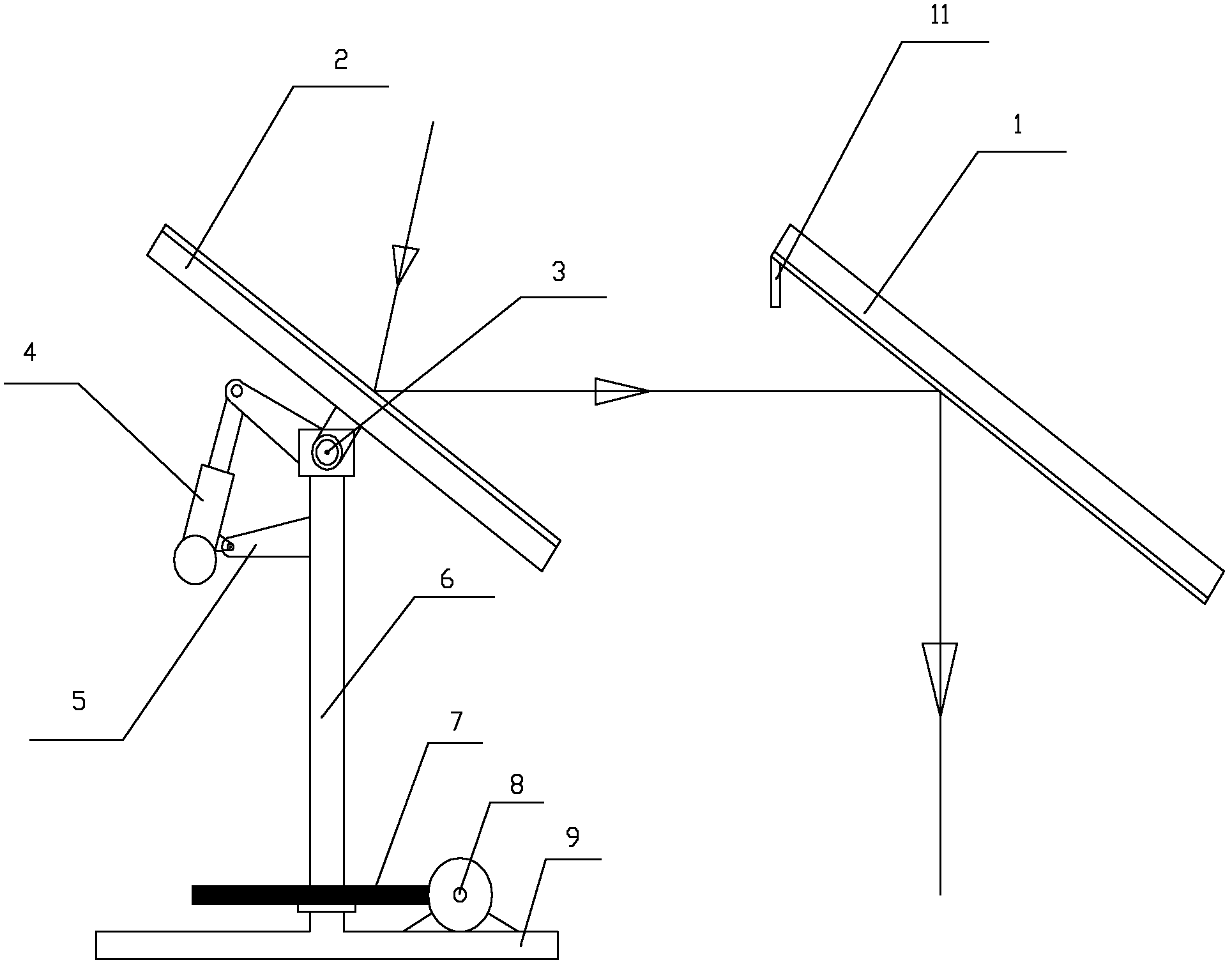
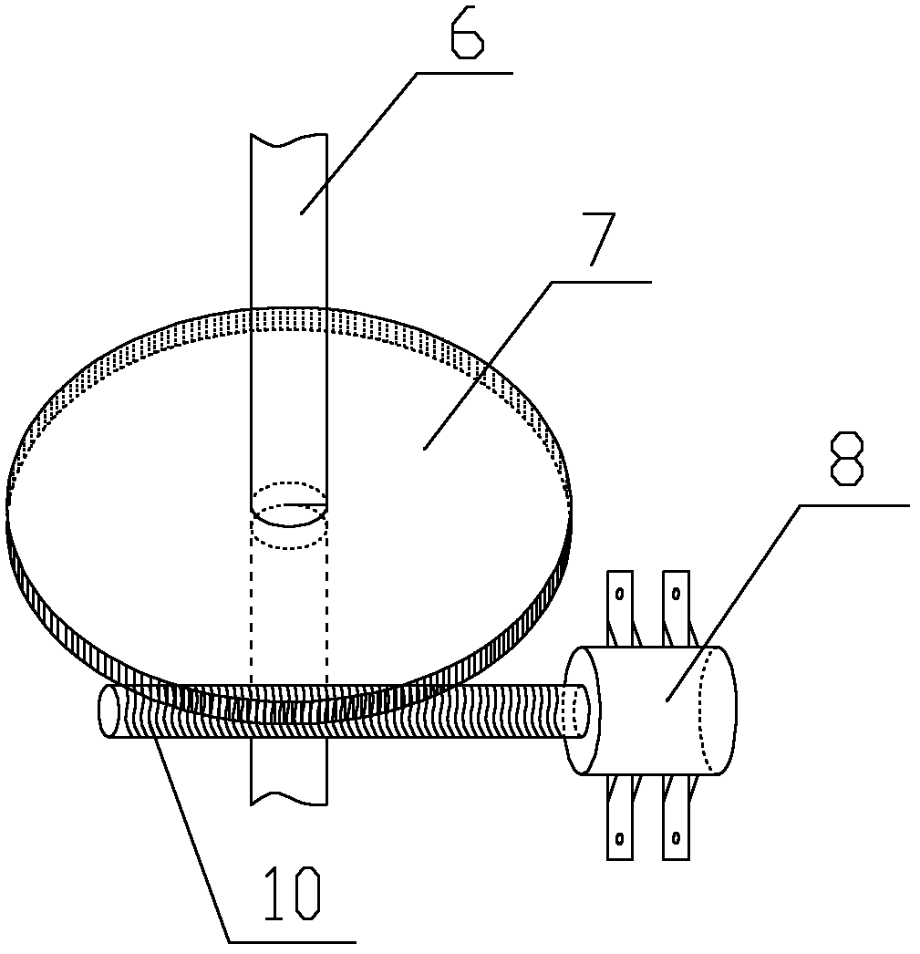
[0009] As shown in the accompanying drawings, the present invention provides an indoor lighting control system, which includes a fixed reflector 1 at an angle of 45° to the ground. The mirror 2 is connected to the vertical shaft 6 through the horizontal shaft 3, and the vertical shaft 6 is connected to the base 9, and the horizontal shaft 3 is also connected to the telescopic rod bracket 5 arranged on the vertical shaft 6 through the electric telescopic rod 4, and the worm motor 8 is installed on the base 9. The worm screw 10 of the motor 8 cooperates with the worm gear 7 arranged on the vertical shaft 6 .

[0010] The photosensitive matrix 11 is located at the top of the fixed reflector 1, and the rotating reflector 2 reflects sunlight to the fixed reflector 1 and the photosensitive matrix 11 at the same time. The photosensitive matrix 11 con...


PUM


Abstract

The invention discloses an indoor illumination control system which comprises a fixed reflective mirror. An angle of 45 degrees is formed between the fixed reflective mirror and the ground. A photosensitive matrix is arranged at the top end of the fixed reflective mirror. The fixed reflective mirror corresponds to a rotating reflective mirror. The rotating reflective mirror is connected with a vertical shaft through a transverse shaft. The vertical shaft is connected to a base. The transverse shaft is further connected on an extensible rod support through a motor-driven extensible rod. The extensible rod support is arranged on the vertical shaft. A worm motor is installed on the base. A worm of the worm motor is matched with a worm wheel arranged on the vertical shaft. The indoor illumination control system achieves the aim of automatic control of indoor illumination by utilizing a sunlight reflecting method.

Description

technical field [0001] The invention relates to an indoor lighting control system. Background technique [0002] With the gradual development of society, the demand for energy in all walks of life has increased significantly. Among them, lighting is a large energy consumer. However, the earth's energy is limited. From the perspective of sustainable development, energy conservation and development of recyclable Energy is a priority. The lighting method using sunlight reflection came into being. The present invention makes further research on how to introduce more sunlight into the room and how to automatically adjust the position of the reflecting mirror to provide stable and continuous sunlight. Contents of the invention [0003] In order to overcome the deficiencies of the above-mentioned prior art, the object of the present invention is to provide an indoor lighting control system, which solves the problem of automatic control of indoor lighting by using sunlight reflec...

Claims


Application Information

Patent Timeline
IPC IPC(8): F21V14/04
Inventor 高磊张雪银
Owner XIAN ELITE ELECTRONICS IND
Why Eureka
Try Eureka