
Multi-crankshaft concrete mixer

A mixer and concrete technology, used in cement mixing devices, clay preparation devices, chemical instruments and methods, etc., can solve problems such as unbalanced operation, affecting the normal operation of mixers, easily causing vibration, etc., to achieve accelerated mixing and high-quality mixing. effect, the effect of increasing the stirring frequency

Active Publication Date: 2013-06-05
润桐(苏州)技术服务有限公司
View PDF5 Cites 4 Cited by
  • Summary
  • Abstract
  • Description
  • Claims
  • Application Information

AI Technical Summary

Problems solved by technology

[0003] The split connection structure connected back to the crankshaft is easy to produce eccentricity during rotation, and it is easy to cause vibration due to unbalanced operation, which in turn affects the normal operation of the mixer

Method used


Image

  • Multi-crankshaft concrete mixer
  • Multi-crankshaft concrete mixer
  • Multi-crankshaft concrete mixer

Examples


Embodiment Construction

[0028] Now illustrate the present invention in conjunction with accompanying drawing and embodiment.

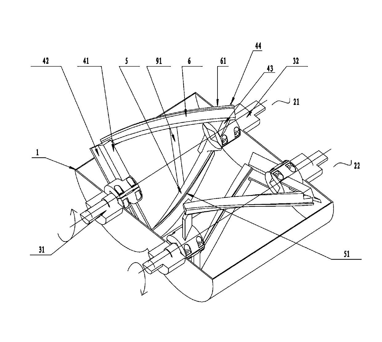
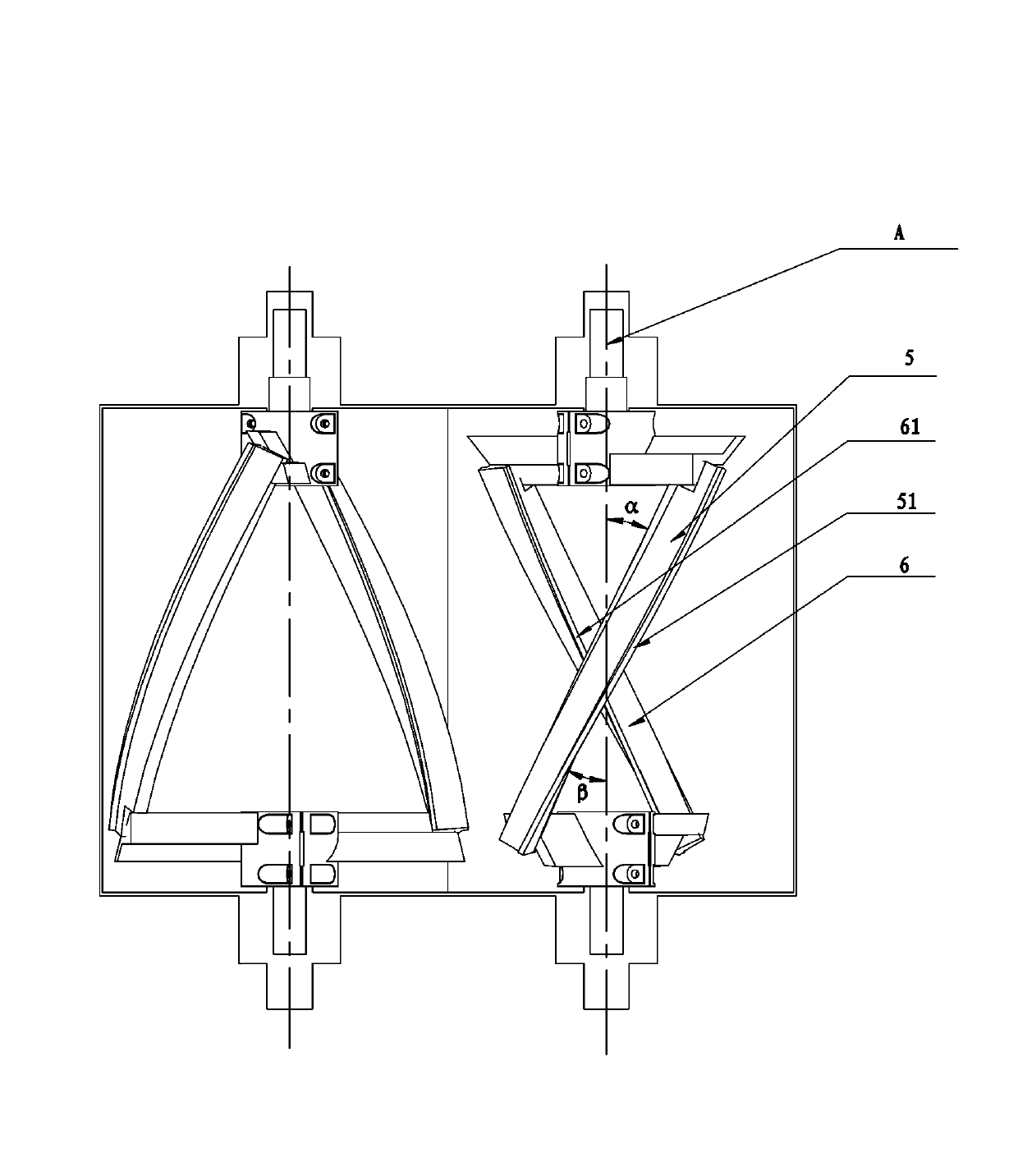
[0029] Such as figure 1 Shown is a multi-crankshaft concrete mixer, which includes more than one mixing device rotatably connected in the mixing drum 1 . Each agitator includes a side feed assembly, a side return assembly and an agitation crankshaft assembly.

[0030] Wherein, the side feed assembly includes a feed agitating arm 41 connected to the drive shaft end 31 of the agitator, and the feed agitating arm 41 is integrally or separately provided with a side feed blade 42 . The side return assembly includes a return stirring arm 43 connected to the driven shaft end 32 of the mixer. The return stirring arm 43 is integrally or separately provided with a side return blade 44 . The side feed vane 42 and the side return vane 44 provided separately are detachable structures for easy replacement. The side feed blade 42 and the side return blade 44 of the present invention are ...


PUM


Abstract

The invention discloses a multi-crankshaft concrete mixer. The multi-crankshaft concrete mixer comprises more than one mixing device connected in a mixing barrel in a rotating mode, and the mounting directions and the rotating directions of two adjacent mixing devices are opposite. Each mixing device comprises a side feeding assembly, a side returning assembly and a mixing crankshaft assembly, wherein the side feeding assembly and the side returning assembly are respectively provided with a mixing arm connected with a main mixing shaft and a returning mixing arm connected with the main mixing shaft, vanes are arranged integrally or in a split mode on the mixing arm. The mixing crankshaft assembly comprises more than one feeding crankshaft, at least, the feeding crankshaft comprises two outer feeding crankshafts which are respectively connected with the feeding mixing arm and the returning mixing arm, and the spiral direction of the two outer feeding crankshafts are the same, and the two outer feeding crankshafts are connected on the mixing arm and distributed systematically. The multi-crankshaft concrete mixer resolves the problem that vibration is large due to large decentration in the prior art, and is stable in operation, low in energy consumption, and high in efficient due to the multi-crankshaft arrangement.

Description

technical field [0001] The invention relates to a spiral mixing device, in particular to a mixing mechanism of a mixer used for mixing concrete. Background technique [0002] The current concrete mixer generally adopts a mixing mechanism running around a horizontal axis, and the mixing device usually adopts a double helical crankshaft structure. Please refer to the Chinese patent document ZL201020614615.0 "a double-helix concrete mixer" published on June 1, 2011. The mixer only consists of a set of stirring devices installed in the mixing drum. Feed crankshaft and inner and outer two return crankshafts are composed, and also include connecting shafts connecting inner and outer feed crankshafts and inner and outer return crankshafts. The device uses the inner feed crankshaft to connect the outer return crankshaft, and the outer feed crankshaft to connect [0003] The split connection structure connected back to the crankshaft is easy to produce eccentricity during rotation,...

Claims


Application Information

Patent Timeline
IPC IPC(8): B28C5/14
Inventor 陈建凡
Owner 润桐(苏州)技术服务有限公司
Learn More