Axial flow fan

A streamlined axial flow fan technology, applied in the field of air conditioners and fluid machinery, can solve the problems of increased air supply noise, environmental noise of air conditioners or ventilation devices, etc.

Active Publication Date: 2013-05-29
GREE ELECTRIC APPLIANCES INC
View PDF6 Cites 7 Cited by
  • Summary
  • Abstract
  • Description
  • Claims
  • Application Information

AI Technical Summary

Problems solved by technology

Since the rear edge of this type of airfoil forms an expansion part, the air flowing out from this part will generate a vortex behind the expansion part, so the noise of the air supply will increase, resulting in the environmental noise of using an air conditioner or ventilation device. question

Method used


Image

  • Axial flow fan
  • Axial flow fan
  • Axial flow fan

Examples


Embodiment Construction

[0034] The embodiments of the present invention will be described in detail below with reference to the accompanying drawings, but the present invention can be implemented in many different ways defined and covered by the claims.

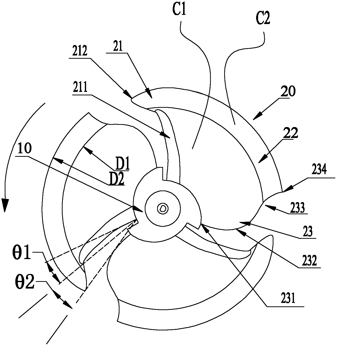
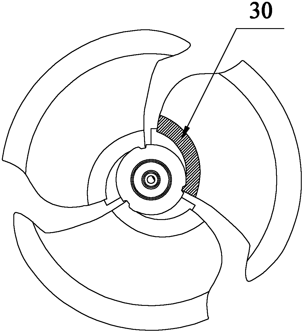
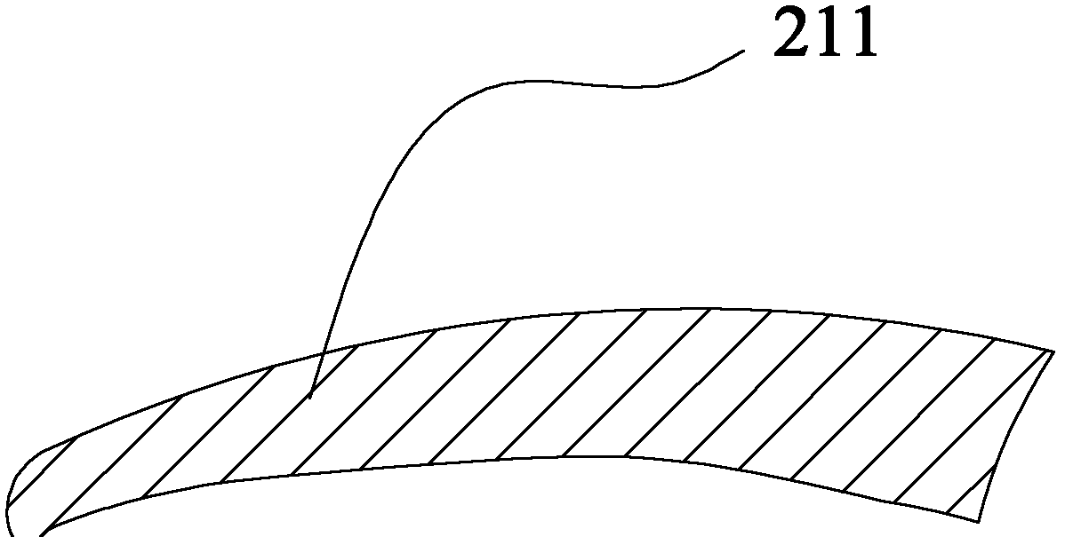
[0035] figure 1 A front view of an axial fan of an embodiment of the present invention is shown. In this example, if figure 1 , Figure 7 As shown, the axial flow fan of the present invention is a three-wing axial flow fan, including a hub 10 as a rotating shaft, and vanes 20 with the same shape that are radially distributed on its outer peripheral side, and the three vanes are arranged at 120° Within the range of ±5°, they are equally spaced or unequally spaced. The front edge of the airfoil 20 is provided with a pressure surface wall thickness reinforced part 211 on the pressure surface side. The thickness of the pressure surface wall thickness reinforced part 211 is thicker than other parts of the airfoil 20. 214 begins to extend along the ...


PUM


Abstract

The invention provides an axial flow fan which comprises a hub and wing pieces. A pressure face wall thickness reinforcing portion is arranged on one side of a pressure face of the front edge of each wing piece and protrudes out of the pressure face of each wing piece. A corner is arranged close to a wing tip of the front edge of each wing piece. The axial flow fan has the main advantages that the thickness reinforcing portion is arranged on each wing piece, interference and turbulent flow are reduced and noise is further reduced; the wing tips are in a forward inclined design, so a surge phenomenon is avoided; and an expansion portion is arranged on the rear edge of each wing piece, and the pressure at the expansion portion is increased.

Description

technical field [0001] The invention relates to the field of air conditioners and fluid machinery, in particular to an axial flow fan suitable for the outdoor unit of the air conditioner. Background technique [0002] Axial flow fans are widely used in outdoor units of air conditioners or other ventilation equipment to circulate air. The basic structure of an existing axial flow fan for an air conditioner is composed of a circular hub with a center of rotation and several fins arranged radially on the outer peripheral side of the hub, and the fins are obtained by a three-dimensional curved surface shape. Driven by the motor to rotate, the air flows in from the leading edge of the airfoil, is boosted by the airfoil, and then flows out from the trailing edge of the airfoil. [0003] Figure 9 An axial flow fan generally used in the prior art is shown, which is composed of a hub 110 and fins 120 . The airfoil 120 has a leading edge 121 , an airfoil 122 and a trailing edge 123...

Claims


Application Information

Patent Timeline
IPC IPC(8): F04D29/32F04D29/38
Inventor 肖忠弟肖彪余锐生艾大云董术海陈民华王雄治叶容君赵伟东王立垚
Owner GREE ELECTRIC APPLIANCES INC
Why Eureka
Try Eureka